When working on electronics or Assembling and Soldering PCBs, an overhead light source makes the process easier and more comfortable on the eyes. Our work table, although situated in a room with many lights, does not have any overhead bright light source. This often leads us to use portable sources of lights such as the flashlight of a mobile phone. Although the mobile phone flashlight gets the job done, an adjustable workbench lamp would be ideal.
Once again there are many 3D Printable designs available online. We wanted to design our own so that we can use the lamp with commercially available light bulbs and fixtures. Also we would have the ability to change the design for different types of light bulbs if we need to.
Our main requirements for our lamp were adjustability and reach of the lamp. We wanted our lamp to be adjustable so that when in use it can be easily extended to where needed and when not in use it can be retracted or moved away so as not to be in the way. Our idea was for the lamp to be mounted to a corner of the workbench. And when needed the lamp can be adjusted and extended to the area of the table where needed. And when not in use it can be retracted to a corner and out of the way.
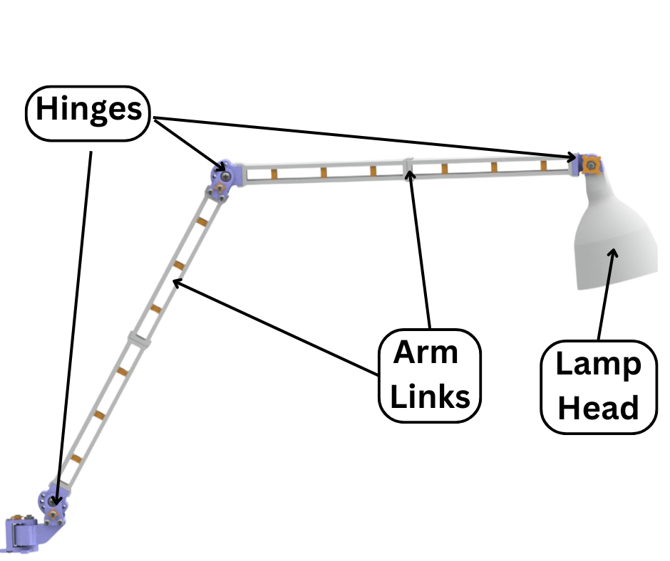
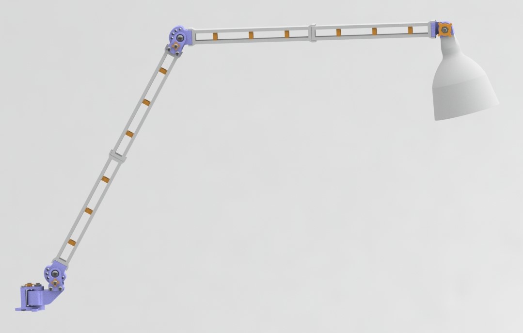
Fig.1
Fig.1 shows our initial design of the lamp. As can be seen it consists of a lamp head housing the light bulb. The lamp head is attached to a hinge mechanism which in turn is connected to an arm linkage. We have two arm links in this design, each with a hinge mechanism to allow adjustability.
This design consists of two hinges to allow extension and retraction of the lamp. A hinge at the lamp head to adjust where the light from the bulb shines. And at the base of the lamp there is a swivel hinge to allow the lamp to be rotated to a desired location when extended. These joint types are shown in Fig.2.
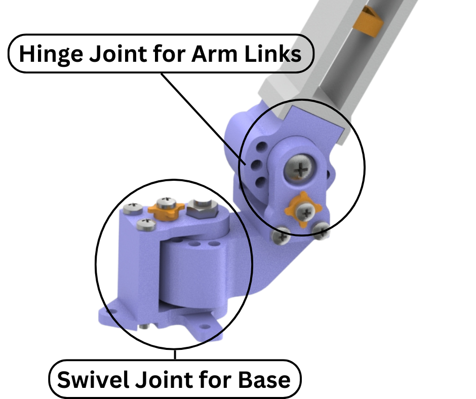
Fig.2
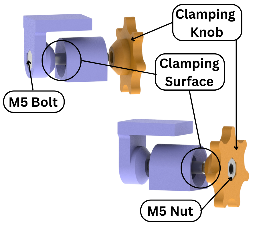
Fig.3
The hinge mechanism of our lamp has gone through multiple revisions. The initial design of the hinge is shown in Fig.3. This hinge mechanism worked on the principle of friction. Loosening the knob allows the hinge to be rotated along its axis. Tightening the knob causes friction between the hinge parts which stops the hinge from rotating. This mechanism is great for handling small loads. During testing we found out that in the retracted position the hinges worked well to support the lamp head and linkages. But in the extended position the weight of the lamp along with the long arm linkage caused too much moment about the hinges for the hinge tightening mechanism to handle. The arm linkage would start to move even though the hinge mechanism is tightened to the maximum.
Fig.4 shows our updated hinge design. This version of the hinge mechanism is more robust albeit slightly less adjustable. With this mechanism the arm linkage connected to this hinge can be moved to some specified positions as shown in Fig.5.
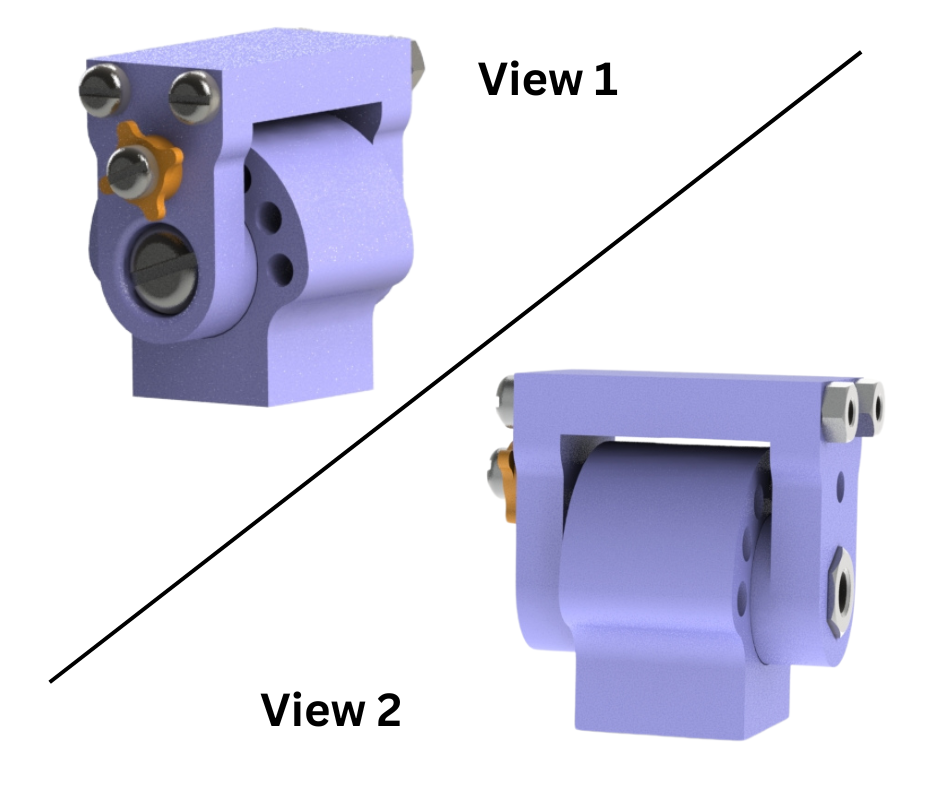
Fig.4
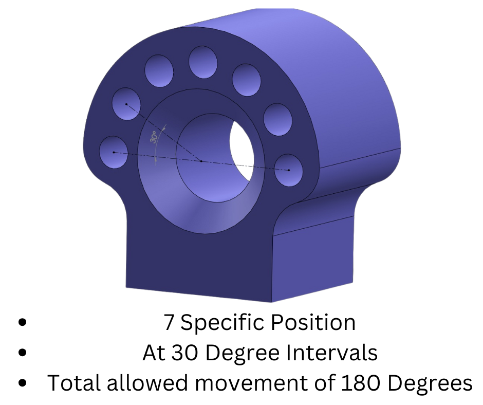
Fig.5
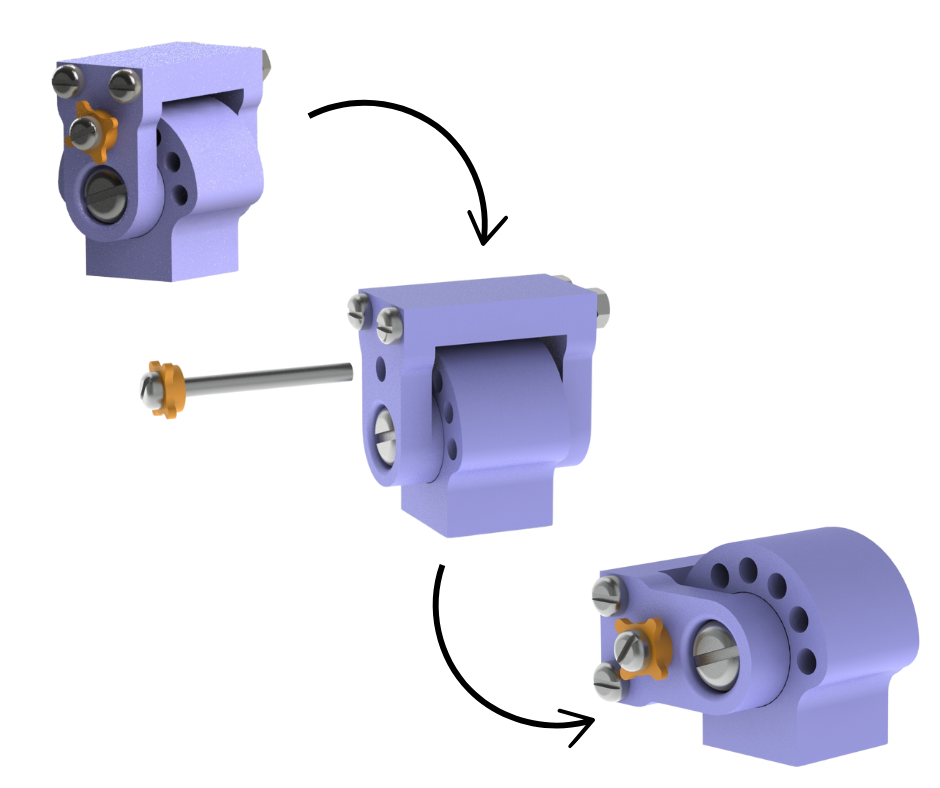
Fig.6
To rotate the hinge the locking pin is first removed. The hinge is then rotated to the desired position and the locking pin is then reinserted in the nearest pinhole location as shown in Fig.6. Since the number of pinholes are limited, it means that a lamp arm linkage can only be set to certain limited positions. But this mechanism makes up for this limitation with robustness and holding strength. This hinge design can bear the large moment forces that it faces when the lamp is in the fully extended position.
This sums up our work on the first version of the 3D printed workbench lamp. We are currently working on cosmetic and functional upgrades to this design. We will post updates on this blog as the upgrades are done and tested.