For some time we needed a small bench vise for our electronic related work such as soldering and pcb making. Previously we had been using a commercially available small aluminium table vise like the one shown in Fig.1.
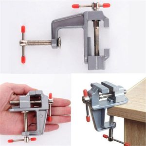
Fig.1
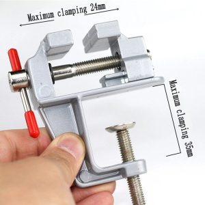
Fig.2
While this vise was small, portable and did the task of work holding well, it had some shortcomings that reduced its usefulness.
- The maximum the vise jaws could open was 24mm as shown in Fig.2. This means that if the width of your workpiece was more than 24mm, you could not hold it in this vise.
- This vise could only be used along a table’s edge.
- Once fixed to a table’s edge this vise cannot be swiveled. This means that you cannot change the orientation of your workpiece while it is held in the vise.
- There is a noticeable gap between the dovetails of the vise and that of the moveable vise jaw. This causes the moveable jaw to twist slightly when gripping a workpiece from an end. This twist in the jaw leads to poor workholding of the workpiece.
To address these problems using 3d printing, we decided to design a 3d printable bench vise. Now there are many 3d printable vise designs available online that can work very well. But we wanted a design that did not utilize dovetails as guides for the moveable jaw of the vise. Reason being that dovetails required a high degree of accuracy while printing to ensure smooth movement of the moveable jaw. Also because the vise dovetails are also made of plastic, there is a lot of friction between the moveable vise jaw and the vise dovetails due to plastic on plastic contact. We wanted to use 8mm stainless steel rods as the guides for the moveable jaw. Having a smooth surface the steel rods would allow a smoother movement of the vise jaws. And being made of steel the guides would be able to handle the twisting forces experienced by the moveable jaw while work holding.
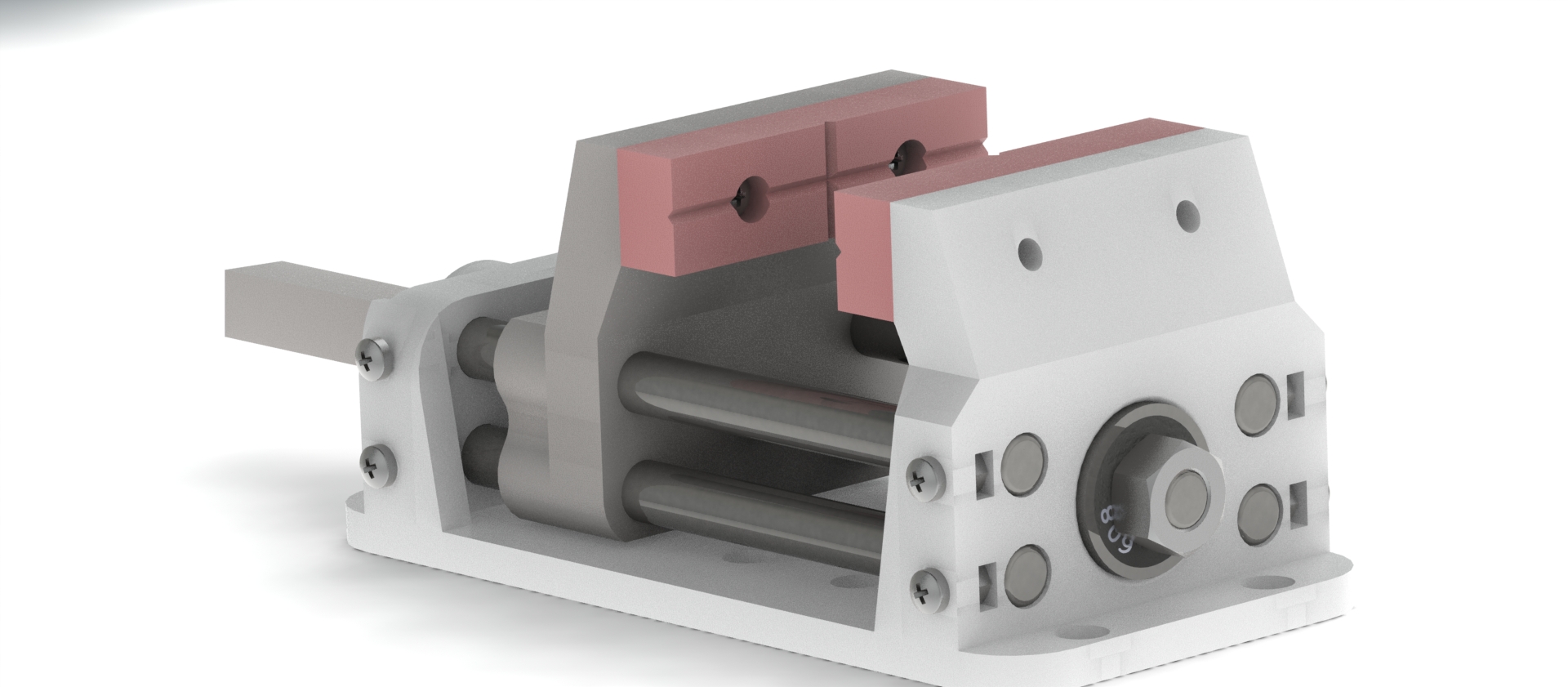
Fig.3 shows our vise design as designed in Solidworks. Fig.4, Fig.5, and Fig.6 highlight some of the features of our vise design.

Fig.3
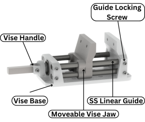
Fig.4
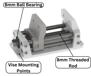
Fig.5
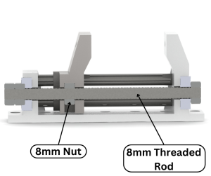
Fig.6
For Actuation of the moveable vise jaw we use an 8mm threaded rod which is secured at both ends of the vise using 8mm nuts. 8mm ball bearings are incorporated into the design to act as thrust bearings for the nuts to tighten up against. The bearings also help keep the threaded rod parallel to the guide rods and also ensures the smooth rotation of the threaded rod. There is an embedded 8mm nut inside the moveable vise jaw which when interfaced with the rotating threaded rod causes the moveable jaw to actuate backwards or forwards depending on the direction the threaded rod is rotating. This can be clearly seen in the cross sectional view of the vise in Fig.6.
We have used 4 stainless steel smooth rods as guides for the moveable vise jaws. These rods are held securely in the vise using 3mm bolts as shown in Fig.4. Using 4 guide rods surrounding the threaded rod in the middle lessens the amount of moment that the moveable jaw experiences when clamping on the workpiece.
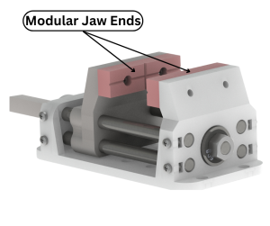
Fig.7
To add more utility to our vise design we have added modular jaw ends to our design as shown in Fig.7. This allows us to add different types of jaw ends to our vise to suit the different geometries of work pieces. For example if we need to hold a workpiece that is cylindrical, we can 3d print jaw ends that are specifically designed to hold cylindrical work pieces.
The vise features multiple points (Fig.5) to attach the vise to an external surface such as a table. As can be seen in Fig.8, we have attached our vise to a piece of wood to give the vise a bit more weight.
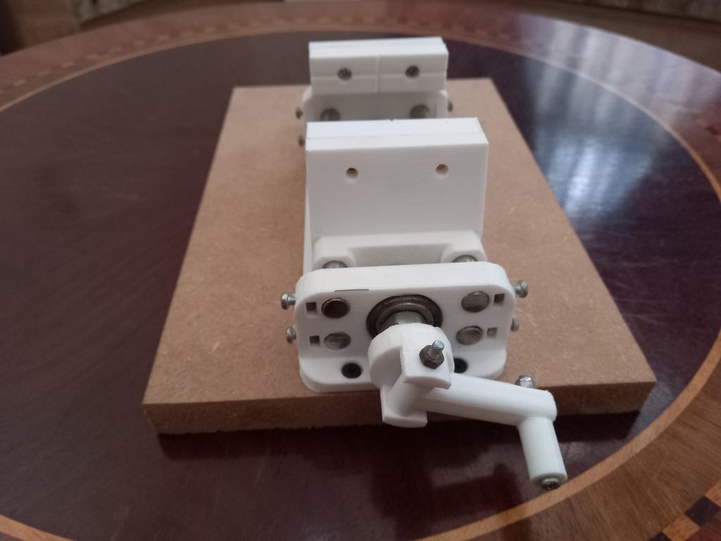
Fig.8
One of the most important features of our design is its large holding capacity. Our vise can accommodate workpieces as thick as 58mm which is more than enough for our needs. If there is a need for more vise jaw opening we can simply reprint the body after making it longer in our design.
Fig.9