Printed Circuit Boards (PCBs) are the backbone of modern electronics, from household gadgets to complex industrial machinery. While large-scale manufacturers mass-produce PCBs, hobbyists, makers, and engineers often opt to create their own PCBs at home for personal projects, prototypes, and learning. With the right tools and techniques, designing and fabricating a PCB at home can be an educational and cost-effective process.
Here’s a detailed guide on how to make your own PCBs at home.
1. Understanding the Basics of PCB Design
Before embarking on the process of making a PCB, it’s essential to understand the components involved in designing and building one.
- Circuit Design: This is the blueprint of your PCB, which defines how components such as resistors, capacitors, ICs, etc., are interconnected. You can create a circuit design using software such as KiCad, Eagle, or EasyEDA.
- Schematic and Layout: Once the design is finalized, you create a PCB layout. This involves converting the schematic into a physical board layout by placing the components and routing the connections (traces) between them.
2. Choose Your PCB Materials
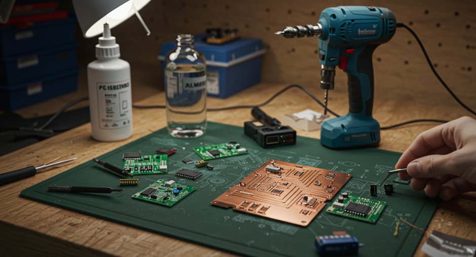
To make a PCB, you need the right materials:
- Copper-Clad Board: This is the base material for the PCB, typically made of fiberglass (FR4) with a layer of copper foil on top. It comes in various thicknesses, but 1.6mm is standard.
- Etching Solution: The most common method for etching PCBs is using an etching solution like ferric chloride or ammonium persulfate. This solution will dissolve the copper from the areas you don’t want on your PCB.
- Photoresist Film or Toner Transfer Paper: These are used to transfer the PCB design to the copper board. Photoresist film requires UV light exposure, while toner transfer uses a laser printer.
3. Designing Your PCB Layout
Use PCB design software to create the layout for your PCB. Here are the steps to follow:
- Draw the Schematic: Start by drawing the schematic of your circuit. Make sure to include all the components and their connections.
- Design the PCB Layout: After finalizing the schematic, translate it into a PCB layout. This step involves arranging the components on the copper-clad board and routing the traces to form electrical connections.
- Generate Gerber Files: Once the design is ready, the PCB software will generate Gerber files. These files describe the layers, copper traces, holes, and other important details needed to manufacture the PCB.
4. Printing the PCB Design
There are two main ways to transfer your PCB design to the copper board:
A. Toner Transfer Method
This method is more popular among DIY enthusiasts due to its low cost and relative simplicity.
- Print the Design: Using a laser printer, print the PCB design onto a glossy paper or special toner transfer paper. Ensure that the design is printed in mirror image.
- Prepare the Copper Board: Clean the copper board with fine steel wool or a cleaning solution to remove any dirt, grease, or oxidation. You should have a shiny copper surface for the toner to adhere to.
- Transfer the Toner: Place the printed paper (toner side down) onto the copper board. Use an iron to heat the paper for several minutes, pressing down firmly to ensure the toner sticks to the board. Alternatively, you can use a laminator for more consistent results.
- Remove the Paper: After cooling down, soak the paper in water and gently peel it off, leaving the toner on the copper surface.
B. Photoresist Method
This method uses a photoresist film, which requires more advanced tools but provides higher-quality results.
- Coat the Board with Photoresist: Coat the clean copper board with a layer of photoresist film. This is typically done by placing a light-sensitive film onto the copper surface.
- Expose the Design to UV Light: Place the photoresist-coated board into a UV exposure box with the printed PCB design in contact with the film. Expose it to UV light to harden the resist where the traces will be.
- Develop the Board: After exposure, immerse the board in a developer solution that will remove the unexposed photoresist, leaving the traces protected by the resist.
5. Etching the PCB
- Prepare the Etching Solution: In a plastic container, prepare your etching solution (ferric chloride or ammonium persulfate) according to the instructions. This will dissolve the exposed copper.
- Etch the PCB: Submerge the PCB in the etching solution and agitate it gently. The copper will start to dissolve, leaving behind only the traces protected by the toner or photoresist. The etching process typically takes 10 to 20 minutes.
- Rinse and Dry: After etching, rinse the PCB with water to stop the process, and then dry it off.
6. Drilling Holes and Cleaning the PCB
- Drill the Holes: Use a small drill or a Dremel tool to drill holes for component leads, such as resistors, capacitors, or ICs. Precision and patience are key to making clean holes.
- Clean the Board: Remove the toner or photoresist (if used) by using a solvent like acetone. Your PCB should now have the copper traces and drilled holes ready for component placement.
7. Soldering the Components
Once your PCB is ready, you can start soldering the components in place. Here’s how:
- Insert Components: Begin by placing the smallest components (resistors, diodes) and work your way up to larger ones (ICs, capacitors).
- Soldering: Use a soldering iron and solder to secure the components onto the board. Be careful not to overheat the board or components. Ensure all connections are solid and inspect for any shorts between traces.
8. Testing the PCB
Once you have soldered all components, it’s time to test your PCB. Connect it to a power source and check for proper functioning. Use a multimeter to check continuity and ensure there are no shorts or open circuits.
Tips for Successful PCB Making at Home:
- Precision: Ensure your design and transfer method are precise. Even a small error in the layout or design can cause the PCB to fail.
- Safety: Always work in a well-ventilated area when using chemicals (etching solution) or high temperatures (soldering).
- Experiment: Start with simple designs and gradually increase the complexity as you become more comfortable with the process.
Conclusion
Making your own PCBs at home can be an incredibly rewarding experience. With the right materials, tools, and techniques, you can create high-quality custom PCBs for your electronics projects. Whether you are a hobbyist looking to build a one-off circuit or a budding engineer creating prototypes, mastering PCB fabrication is a valuable skill that can open up new possibilities for electronics design.