Servos are the most important component in any robotics or automated system because they provide positional accuracy to any part or link they are connected to. If any mechanical mechanism needs to move from point A to point B accurately and repeatedly then you can be sure that servo drives will be used.
When it comes to servos we are very familiar with commercially available servos (Fig.1) that come in different sizes depending on power requirements. They all have the electronics built in and out of sight with just the usual three pin connector output for easy interfacing and control as shown in Fig.2.
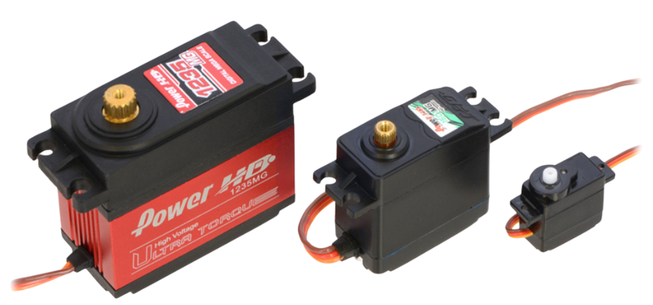
Fig.1
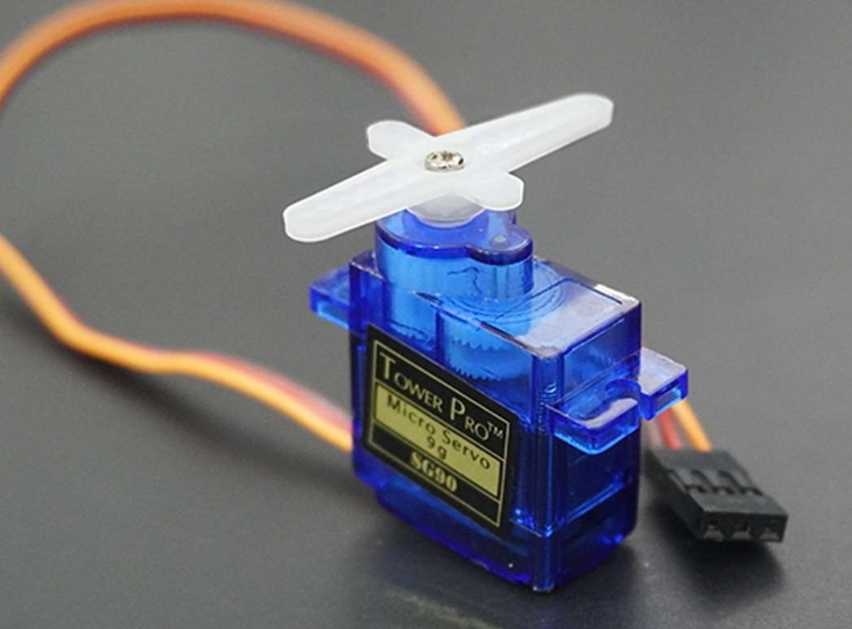
Fig.2
As the torque requirements of a project increases so does the cost of these commercially available servo drives. Sometimes the cost increases exponentially. In addition to high costs, you will also need to design your projects around the footprints of commercial servo drives. This can be an issue if mounting space is limited or the available space has odd geometry. In such cases custom designed servo drives can be implemented. A servo mechanism can be designed into a project according to the space and torque requirements.
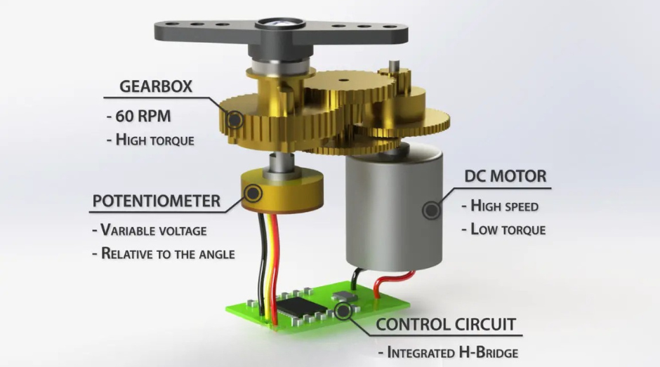
Fig.3
Now we will discuss what a servo mechanism comprises. Fig.3 summarise the basic components of a servo drive. You have a DC motor connected to the output shaft through a gearbox that reduces the speed and increases the torque of the output shaft. There is also a potentiometer that is connected directly to the output shaft that measures the rotational angle of the output shaft. The potentiometer and the DC motor are both connected to a control circuit that takes reading from the potentiometer and uses PID (proportional integral derivative) control algorithm to control the output of an H-bridge to drive the DC motor.
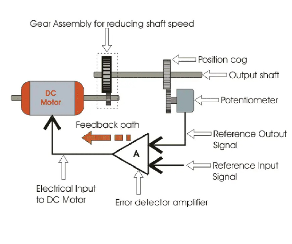
Fig.4
The control circuit also takes an additional control signal input that is the desired rotational position of the output shaft. As can be seen in Fig.4 the servo control circuit takes this input signal and compares it to the readings from the potentiometer connected to the output shaft. The difference in the signals determines how much and in which direction the DC motor is to be run. When the output shaft reaches the desired position the DC motor is stopped. If the output shaft moves away from the desired position due to force being applied the control algorithm will activate and work to bring the shaft position back to the required position. Now if the force on the output shaft is too great then the servo will lack the torque needed to maintain the desired position. So for this purpose an appropriate gearbox can be designed to cater for the forces that are to be expected at the output.

Fig.5
For our rover project that you can read in our projects blog, we worked on designing a custom servo drive to control the steering of the six wheels of our rover. The wheel mount of our rover was connected to the main chassis of the rover via a 3D Printed thrust bearing as shown in Fig.5. For our servo drive we used a 3 to 1 reduction gear system where the output gear controlling the steering of the wheel mount has 36 teeth while the drive gear connected to the DC motor has 12 teeth. The reason we did not use more gearing ratio in our design was because the DC motor we were planning to use was itself a geared DC motor. The large output gear was designed to be large to act as the bottom plate of the thrust bearing assembly that connects the wheel mount to the rover chassis. Incorporating the thrust bearing into the design of the servo saved space and reduced the complexity of the overall design. This highlights one of the major advantages of designing custom servo drives.
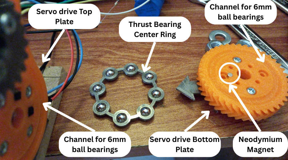
Fig.6
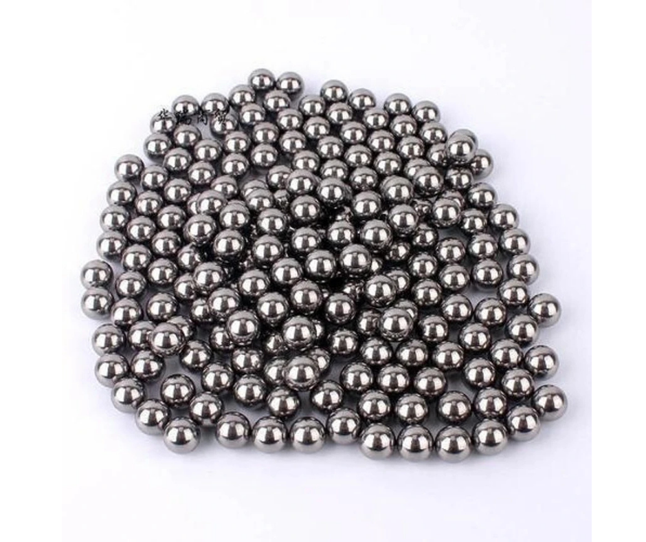
Fig.7
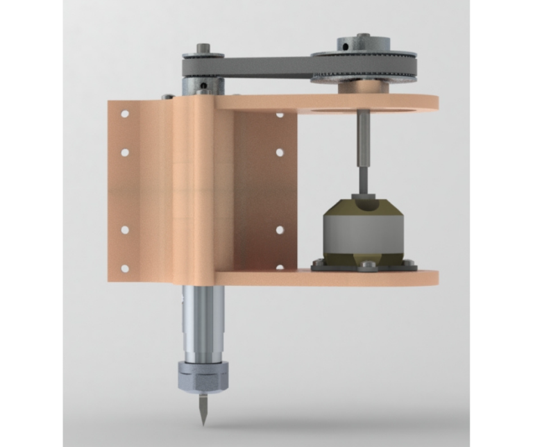
Fig.6 shows the different components of the servo drive assembly with built in thrust bearing. The assembly consists of three 3D Printed parts. First is the top plate that houses the DC motor and potentiometer of the servo drive. Second is the central ball bearing ring that holds eight 6mm (Fig.7) ball bearings in place evenly spaced. The bearings are able to spin in their own positions owing to the design of the ring. The third part is the bottom plate that has the large gear of the servo drive. The bottom plate connects to the rover wheel assembly while the top plate connects to the main rover chassis. As can be seen in Fig.5 the servo assembly, wheel assembly and the main chassis are all connected together using an 8 mm threaded rod and nuts. The purpose of the threaded rod is to keep all the components in their designated places and to prevent them from coming apart. To allow the individual parts to rotate freely there are 8mm radial bearings in the wheel assembly and rover chassis where the 8mm nuts are tightened. The integrated 3D printed thrust bearing allows all the parts to be tightly pressed together while still being able to rotate about the threaded rod.
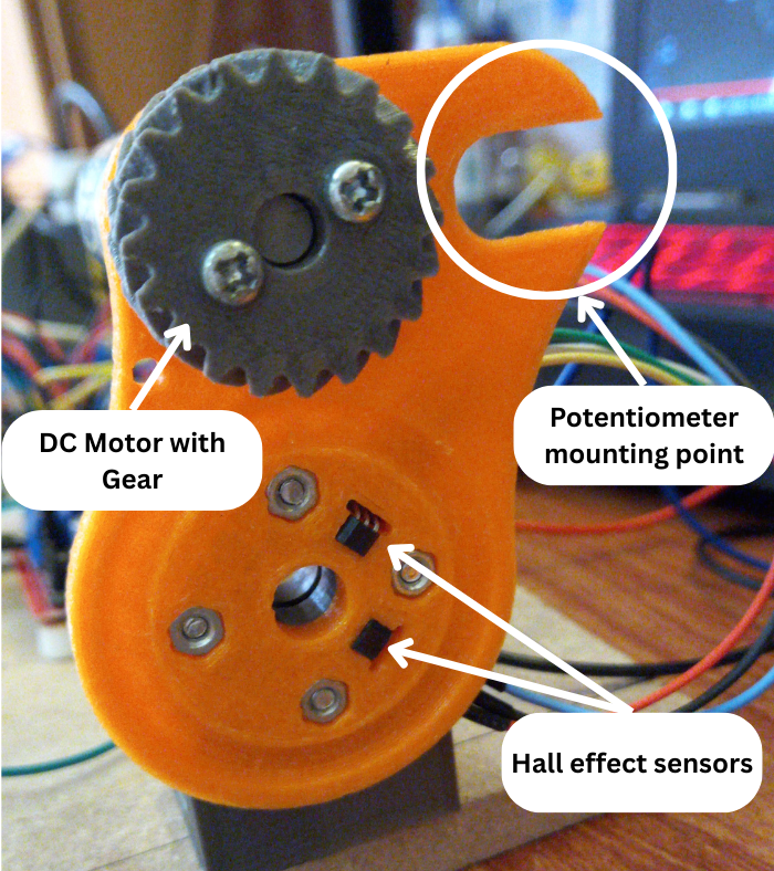
Fig.8
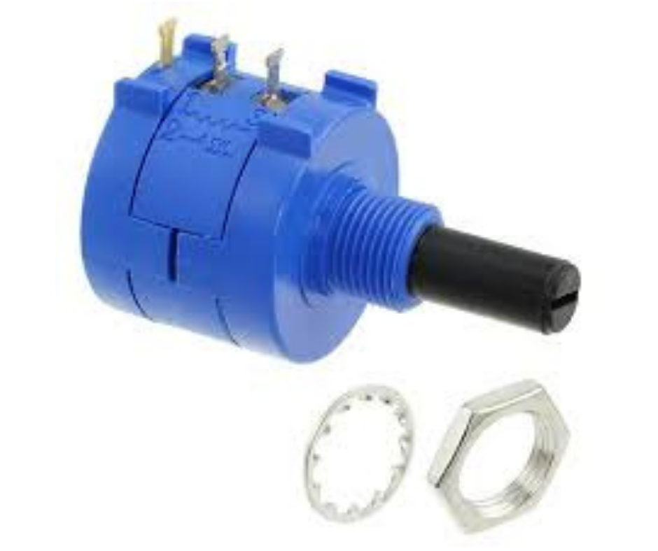
Fig.9
Fig.8 shows the top plate of the servo drive. The top and bottom plates both have integrated channels for the ball bearings to be seated and to move in for the thrust bearing to function properly. The top plate has a DC motor with a 12 teeth drive gear installed in it. This gear interfaces with the integrated 36 teeth gear in the bottom plate to provide a 3 to 1 gearing ratio. The top plate also has a mounting point for a 10 turn potentiometer shown in Fig.9. A 12 teeth gear similar to the drive gear will be installed on the shaft of the potentiometer. This potentiometer gear will then interface with the DC motor drive gear. Since the number of teeth are the same the gearing ratio will be 1 to 1. The top plate of the drive also has to hall effect sensors installed as well as shown in Fig.8. These sensors are there to detect whenever a neodymium magnet passes over it. These sensors are installed to detect the magnet installed in the bottom plate of the servo drive as shown in Fig.6.
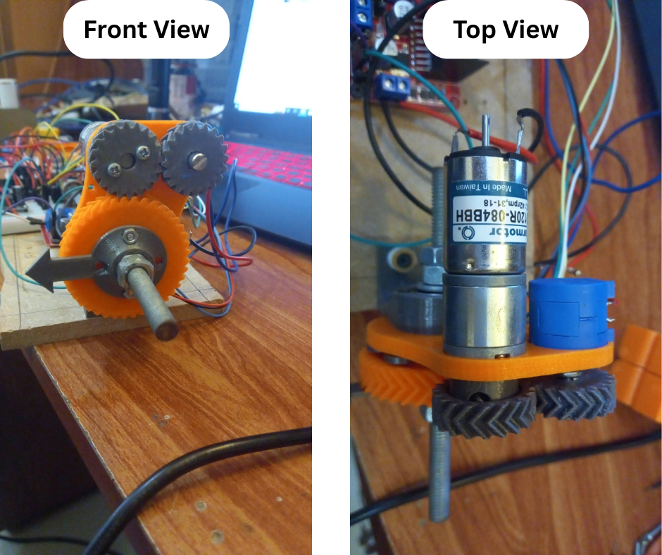
Fig.10
Fig.10 shows the prototype servo drive assembled for testing from the top and front view. The top view shows how the DC motor and the potentiometer are installed onto the top plate of the servo drive. Now we will discuss how a servo determines its angular position from the potentiometer readings. The potentiometer outputs a voltage value which lies between 0V (Ground) and +5V (VCC). When a potentiometer shaft is rotated clockwise the output voltage rises from 0V at its most anticlockwise position to +5V at its most clockwise position. Multi turn potentiometer shafts can rotate a full 360 degrees but single turn potentiometers can not. Normally single turn potentiometer shafts can rotate at least 270 degrees which is more than enough for servos that normally have a rotation range of 180 degrees. In commercial servos, potentiometer output voltage is noted when the servo output is at 0 degrees, at 90 degrees and at 180 degrees. These readings are then programmed into the logic of the control circuit. In the control circuit these readings are linearly mapped so that 0V corresponds to 0 degrees, 2.5V corresponds to 90 degrees and 5V corresponds to 180 degrees. Now more complex servos may use a more sophisticated method but the principal is the same. This is how a control circuit of a servo knows the angular position of the output shaft.
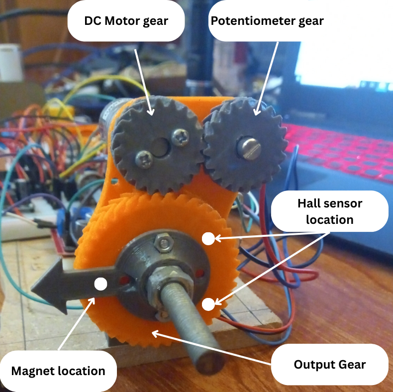
Fig.11
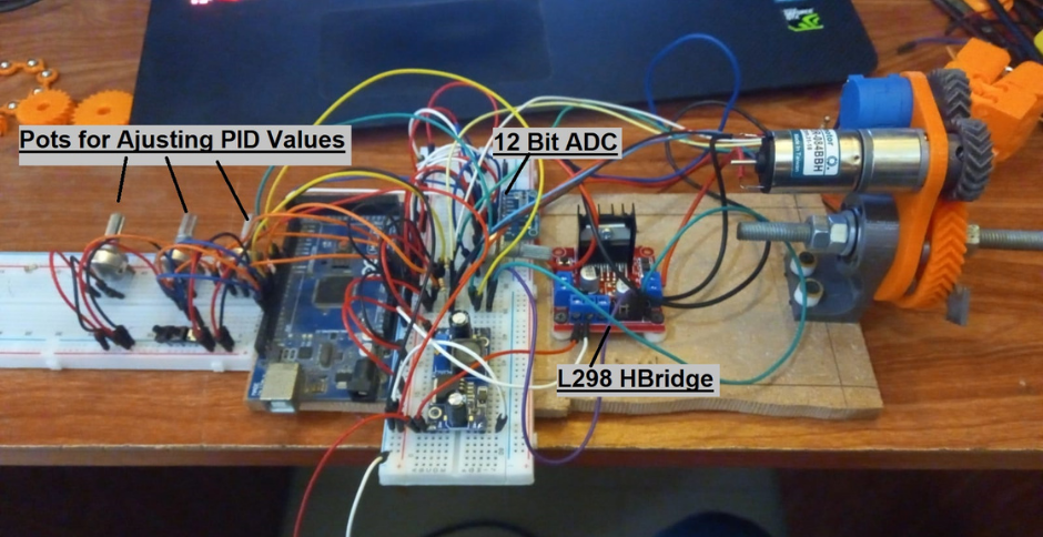
Fig.12
In our servo drive we wanted to avoid having to manually measure the potentiometer readings at different output rotational positions. To achieve automatic calibration of our servo drive, we used hall effect sensors and magnets to determine the potentiometer readings at either rotational endstops. Fig.11 shows our testing setup of our servo drive. The positions of the magnet in the bottom plate and the hall sensors in the top plate are also indicated. The hall sensors are positioned such that there is a major arc angle of 270 degrees between them. This means that going from one sensor to the other along the major arc would yield 270 degrees of rotation. When our servo powers on it first runs a calibration sequence. The servo first rotates the bottom plate with the magnet anticlockwise until the magnet reaches the first hall sensor. The sensor detects the magnet and halts the rotation and records the potentiometer reading. The servo then rotates in the clockwise direction until the magnet in the bottom plate reaches the second hall sensor. The second sensor also detects the magnet and records the potentiometer reading and halts the motor. These readings are recorded by our servo drive microcontroller circuit shown prototyped in Fig.12. The microcontroller then maps the two readings to -30 degree and 240 degree which totals 270 degree of rotation. The mapping is linear so all potentiometer readings that lie between the two initial readings can be easily mapped to corresponding angular positional values. After this initial calibration sequence our servo drive can now ascertain its angular position from its potentiometer readings like any other servo. The control mechanism by which our servo drive controls the DC motor to achieve the desired angular position is the same as other servos as discussed in the beginning.
Now the question is, does this system work? Well mechanically and electrically it works and works well. The issue that hampers the overall accuracy is the detection radius of the hall sensor. Our logic assumes that the sensor should detect when the magnet passed over the center of the sensor. But this is not the case. The sensor picks up the magnet when it is sufficiently near to it. This means that the two readings recorded by our microcontroller do not correspond exactly to 270 degrees of travel. It is slightly less than that. This introduces a slight error in our positions. For example if we ask our servo to go to the 180 degree position it may go to 177 degrees which the servo will think is 180 degrees. Incidentally the servo can go to the 90 degree position accurately because it lies exactly in between the two extremes no matter how off the initial readings are. We do however have a solution for this that we will explore and document in another post. This proof of concept worked well to lay the groundwork on which to improve our subsequent custom servo designs.
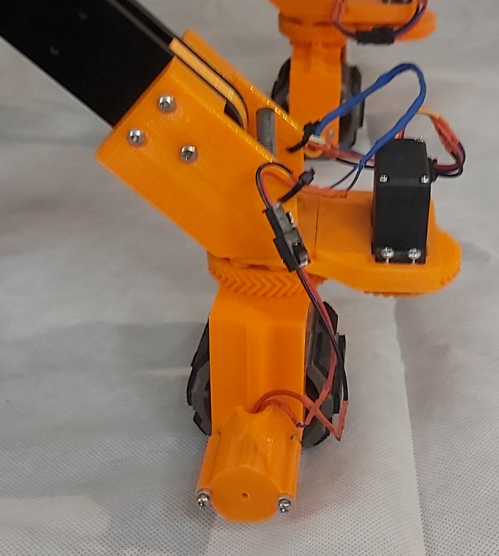
Fig.13
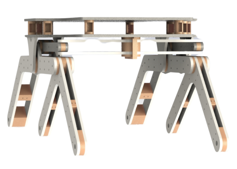
In regards to our rover, for now we went the route of using a commercial servo for our steering mechanism as shown in Fig.13. We did end up using a more powerful metal geared servo for each of our four steering columns. There were two major reasons for not going the custom servo route. First is the error issue in our prototype design using magnets and hall sensors. Resolving that issue required further testing and design changes which our schedule didn’t allow at that time. Second reason was the cost of each servo drive as compared to the commercial servo. The total cost which included the cost of the DC moter, multi turn potentiometer and all the electronics including the arduino and the 12bit ADC, was more than the cost of the commercial servo. Not to mention the hassle of all the wiring and interfacing. But this does not mean that we will be abandoning the custom servo concept. We are working on improving it and trying to reduce its overall cost to make it a more viable option in out upcoming research, projects and products.