When I initially thought of starting Technovation Labs, it had nothing to do with 3D Printers, 3D Printing or Rapid Prototyping. Instead I was more interested in working on developing locally manufacturable STEM (Science, Technology, Engineering and Mathematics) products that catered to the young children and students to inculcate in them vital skills such as programming, troubleshooting, engineering and logic and reasoning. This interest stemmed from my educational background as an electrical and later mechatronics engineer.
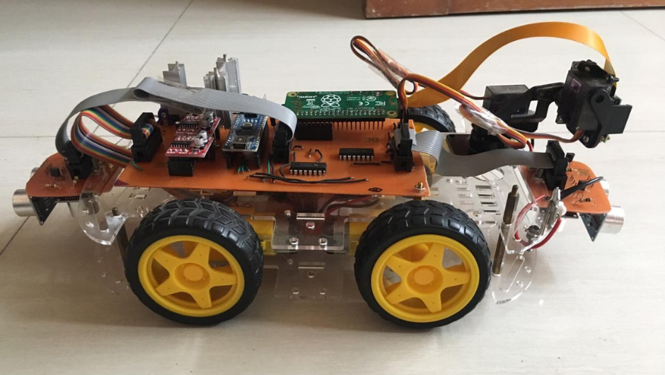
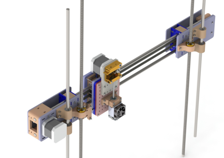
Fig.1
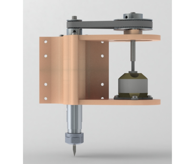
Fig.2
To this end I began working on a small modular and modifiable robotics platform as shown in Fig.1. This project used a commercially available robotics chassis as shown in Fig.2. This chassis consists of laser cut acrylic parts that assemble into a chassis that has mounts for four motors with wheels and multiple holes and cutouts to attach electronics. My intent was to focus on designing electronic systems and addons for this robotic chassis and package all of that into kits. I wanted the kits to be easy to assemble, modify and upgrade as needed by the end user. The details of this project and the process of manufacturing its Printed Circuit Boards in house will be a topic for another post. The main issue I was facing at that time was not the electronics or engineering aspect but the cosmetic aspect of the kits. This project contained a lot of bare PCBs and wiring that not only didn’t look good aesthetically but also was prone to damage if mishandled.
To remedy this problem, I initially started looking for commercially available enclosures that I could modify to suit my needs. But enclosures were only available in very limited sizes and in either square or rectangular shapes. So I began looking for ways I could design and make my own electronics enclosures. As mentioned above, since I was already familiar with how acrylic sheets could be laser cut or machined into parts and then assembled together to create three dimensional structures, I began looking for ways I could do the same in house. A commercial CO2 based laser cutting machine was a bit beyond my budget at that time. And I had come across videos of small desktop sized CNC machines during my research. These were being used to not only machine soft materials such as acrylic but also mill printed circuit boards. This piqued my interest because it seemed to solve both my aims of making custom enclosures and PCBs in house.
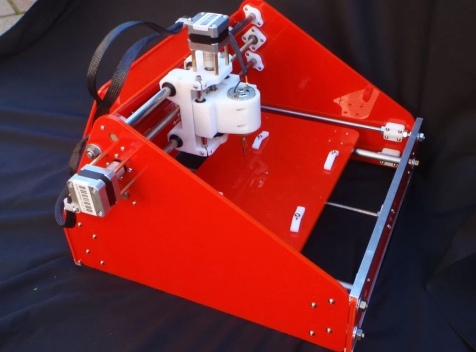
Fig.3
Although there were commercially available small desktop CNC machines, they were either too expensive or had very poor reviews regarding their performance. So once again I chose the route of making one myself so that I could familiarize myself with the mechanics and electronics of the machine and improve it if need be. I found many open source designs for making small CNC machines. I chose the design shown in Fig.3 by “liquidhandwash” on Thingiverse. This open source design was ideal because it used locally available mechanical parts such as rods, bearings and fasteners. And its documentations and assembly instructions were complete and descriptive. The design also contained many 3D printed components. Since I did not have a 3D printer at the time, I searched for local 3d printing companies that could make these parts for me. There were a few companies offering 3d printing services, but after sending them the STL files of the parts, the price they quoted me was almost the cost of a beginner 3d printer.
Intending to build more than one desktop CNC machine, I decided to invest into getting a 3D printer of my own so that I can manufacture the 3d printed parts myself. In Pakistan at that time due to import restrictions and control, 3D printers, even beginner ones such as the ender series were priced highly. A basic ender 3 cost $200 to $300. Therefore there were some local manufacturers who were building prusa i3 clones with the vertical frame and supporting panels made from 6mm thick acrylic. Since they were manufactured locally these printers had a relatively low price and since I had no experience with 3D printers, they seemed like a good choice to experiment and tinker with before going for the more expensive imported ones. So after placing my order for a 3d printer with a local manufacturer, I received my order after a week or so. Unfortunately during transportation the printer frame was damaged in many places as shown in Fig.4 and Fig.5. After repairing the frame as best I could, I began to study the design, construction and working principles of the 3d printer.
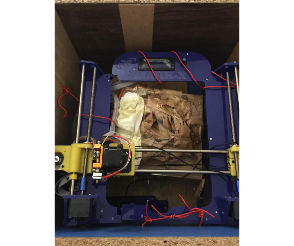
Fig.4
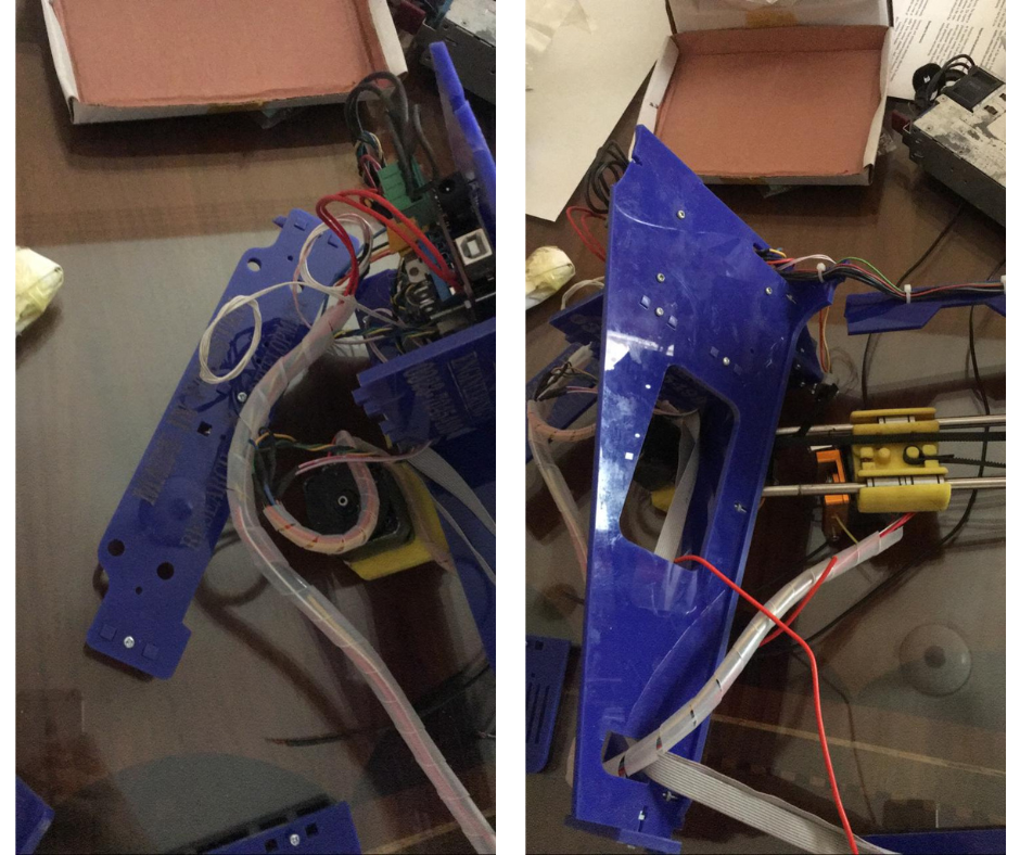
Fig.5
After tinkering for some time with the 3d printer I had bought, I found a lot of shortcomings, flaws and defects in it. The major problem was obviously the damaged frame and structure of the printer which even when repaired was causing alignment and binding issues. The manufacturer also had not installed a heatsink or cooling fan on the extruder nozzle. This severely limited the print time since the hotend would get hot enough to start deforming its 3d printed mount. Also the electronics were mounted directly to the 3d printer main frame and not enclosed in a box. This exposed all the electronics and wiring which could be a shorting or a shock hazard.
Having noted all these issues and also encouraged with the simplicity of the prusa style design, I thought to myself how hard could it be to make a reliable 3d printer. Little did I know that this thought was the beginning of a whole new adventure. Following this impetus I set out to make my own 3D Printer and that was the beginning of my foray into the wonderful and exciting field of Rapid Prototyping.