If you are interested in reading about how I stepped foot into the field of Rapid Prototyping, I would recommend reading the blog post titled “Prelude to my first 3D Printer: The Beginning”.
So like with everything else, I began with research and planning. Most of the available designs for DIY I3 style 3D Printers followed the reprap philosophy which involves using a 3D printer to make more 3D printers. This meant that if I wanted to make my own printer I would need to either have a 3d printer or get parts 3D printed which brought me back to the same issue that I had when trying to make my CNC machine. So I began searching for a design that preferably did not use 3D printed parts. Fortunately I was able to find an open source design on instructables by an Iranian creator (Noyan Pajoohesh shahvar) who had designed a 3D Printer that only used laser cut acrylic parts along with the usual mechanical and electrical components. This was very fortunate because in Pakistan commercial acrylic laser cutting is very common and used extensively for all types of sign and plaques. This meant that the cost of having all the required acrylic parts laser cut was a fraction of what it would have cost to get parts 3D printed.
Next I sourced all the required mechanical and electrical hardware that the 3d printer requires. These are listed below.
Mechanical hardware required:
- 8mm threaded rods
- 8mm linear rods and linear bearings for the three axes
- Pulleys (Drive and idler) and GT2 belts for the X and Y axis motion system
- 8mm Leadscrews for the Z axis
- 3mm bolts (various lengths) and nuts as fasteners
- Springs for the print bed
Electrical hardware required:
- Arduino mega with RAMPS1.4 shield as the brains of the printer
- Graphical LCD
- Limit switches
- 12v 20A power supply
- 12v print bed heater
- Stepper motors and drivers for the three axes
- Mk8 style direct drive extruder with stepper motor
- Connectors and wires
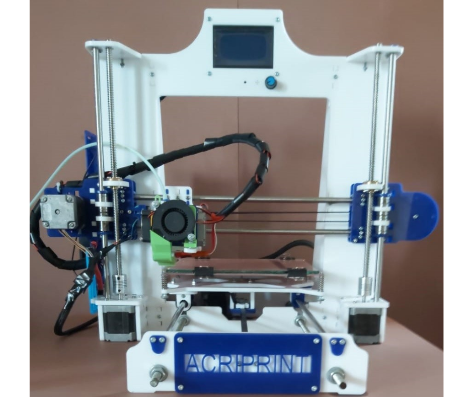
Fig.1
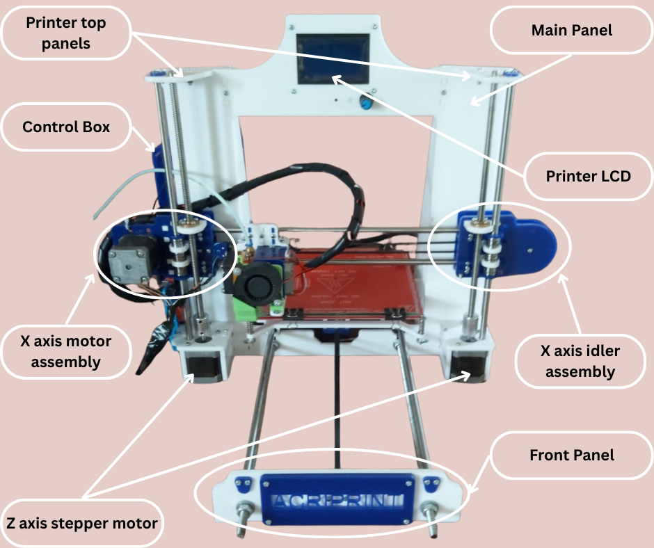
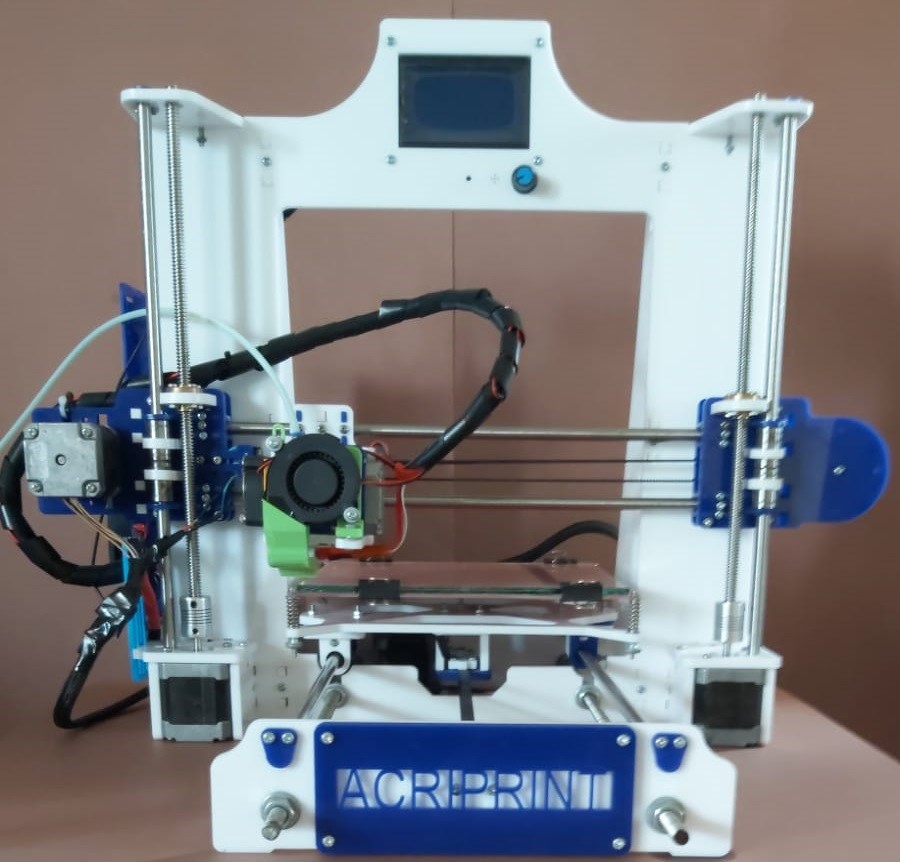
Fig.2
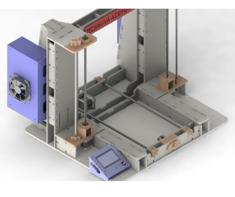
Fig.2 and Fig.3 show my assembled 3D printer. My design is a modified and upgraded version of the open source design by Mr Noyan. His design was made with the intention of replacing components such as the X axis stepper motor and idler mount with 3d printed parts once the printer was operational. Therefore some aspects of his design such as the X axis linear rod mounts were designed to be temporary and makeshift. I changed the open source design to make it more permanent and not in need of 3d printed parts later on. I will now discuss features of this 3D printer along with some improvements that I made to the open source design.
As can be seen in Fig.2 and Fig.3, the overall design is based on the hugely popular prusa i3 style of 3D printers. This printer is a cartesian printer which means that the print bed moves in the Y Axis and the extruder moves in the X and Z axis. This design of 3D printers is sometimes also called a “bed slinger” because the print bed also moves.
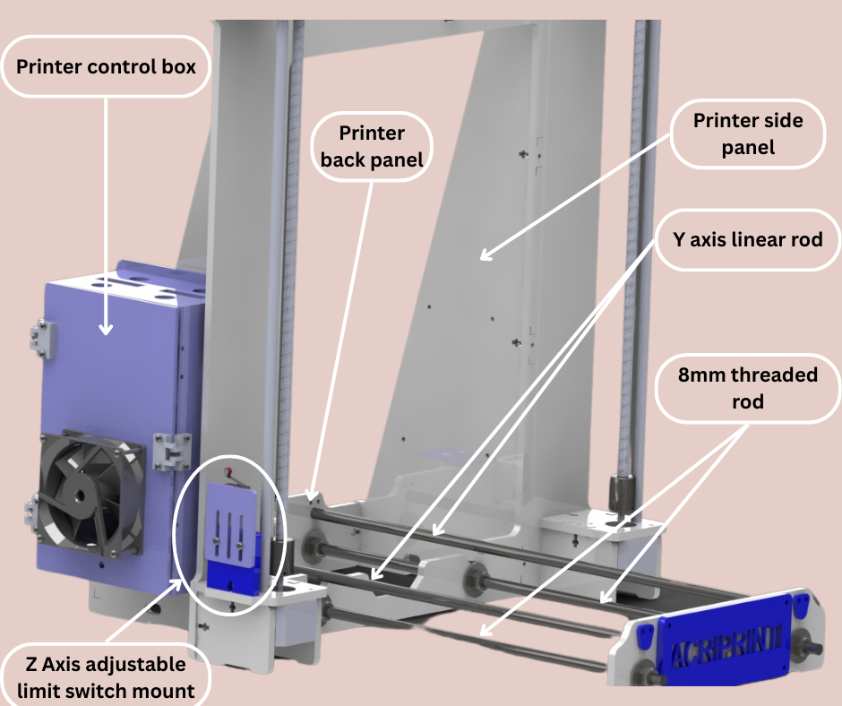
Fig.3
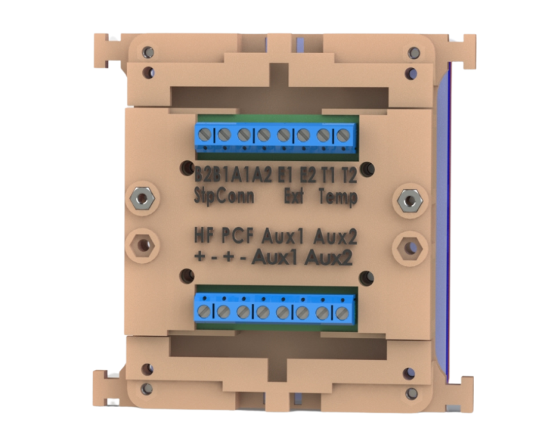
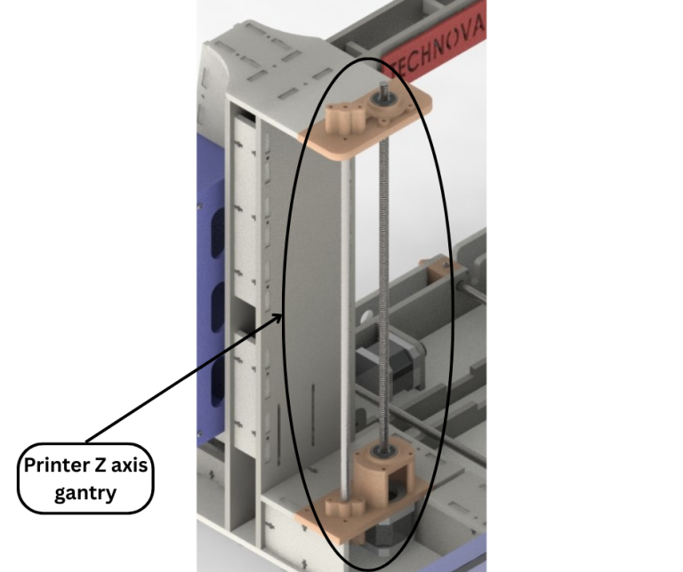
The 3D printer structure consists of a main panel which is the largest panel of the printer and also houses the printer LCD at the top as shown in Fig.2. This main panel connects to the back panel and side panels as shown in Fig.3. The back panel has a mount for the Y axis stepper motor as seen in Fig.4. The main panel also has stepper motor mounts for the two Z axis lead screws and also connects to the top panels which provides support to the Z axis linear rods and lead screws. The main panel, side panels, top panels and back panel all connect together using 3mm bolts and nuts to form the main structure of the 3D printer as shown in Fig.2 and Fig.3. The front panel of the 3D printer connects to the main structure via two 8mm threaded rods, nuts and washers as shown in Fig.3. This combined structure forms the overall frame of the 3D printer. The front and back panels of the frame provide mounting points for the Y axis linear rods as seen in Fig.3. The original open source had all the electronics in the open. I designed a control box that houses all the printer electronics. The box is shown in Fig.3 and is mounted to one of the side panels of the printer frame. This control box is also made entirely from laser cut acrylic panels which are joined together by adhesive.
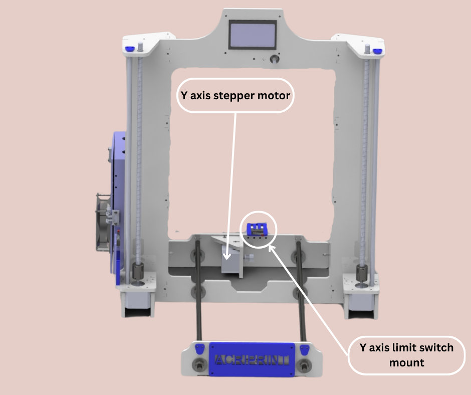
Fig.4
Another improvement that I made to the original design was to add adjustable limit switch mounts for the Y and Z axis. These can be seen in Fig.3 and Fig.4. These mounts with their respective limit switches allow fine tuning of the positions of the Y and Z limit switches. Similar adjustments can be made to the X axis limit switch as well. These upgrades are important because if the extruder is changed in the future then the start point of the printer coordinate system will change and these upgrades allow the start point to be adjusted back to the origin.
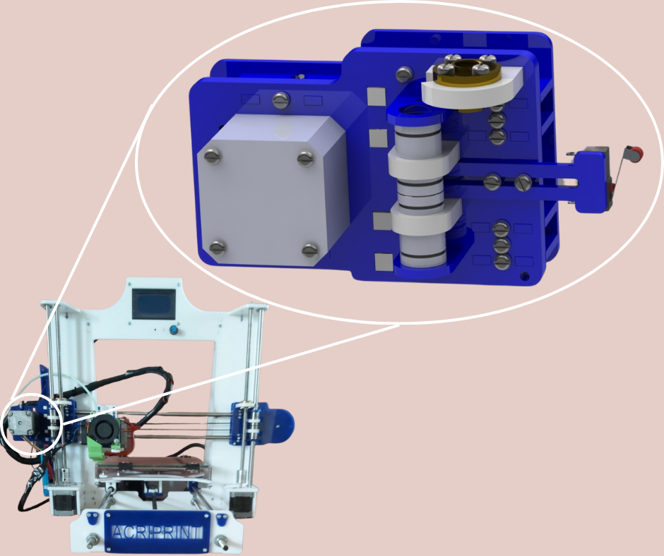
Fig.5
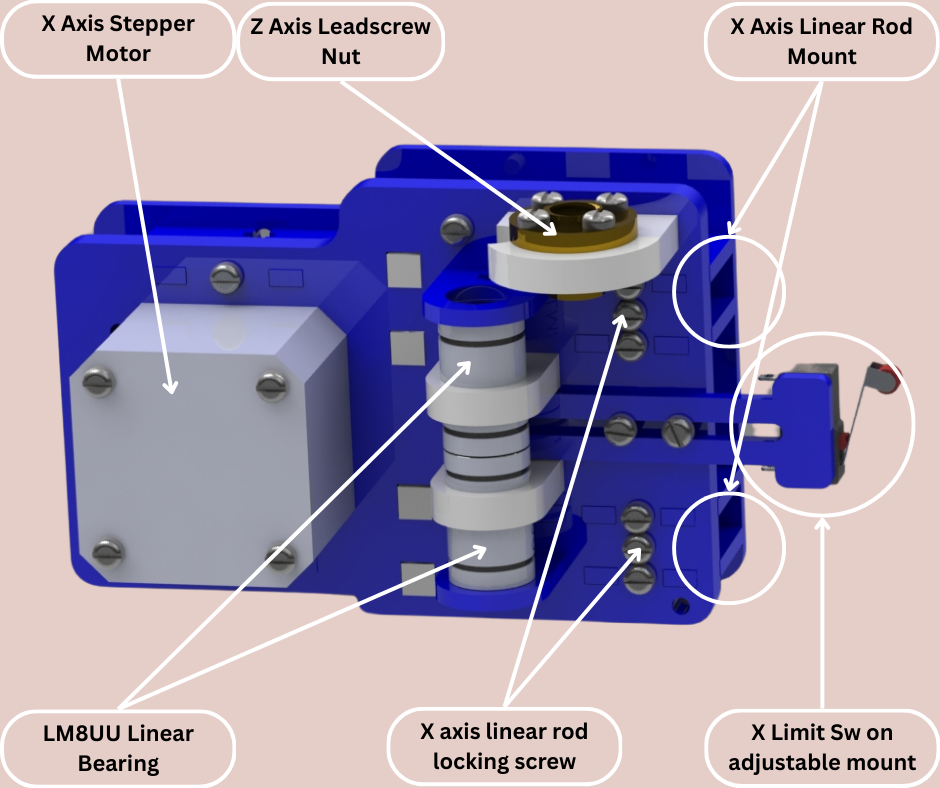
Fig.6
The X axis of this 3D printer consists of the X axis motor mount assembly, the X axis idler assembly and two 8mm linear rods. The design of the X axis motor assembly (Fig.5) is largely the same as the X axis idler assembly. So we will discuss the design of the X axis motor assembly. This assembly is shown in more detail in Fig.6. This assembly consists of many laser cut acrylic parts joined together using 3mm bolts and nuts. The assembly consists of two lm8uu linear bearings held in place with acrylic clips. The linear bearings are used by the assembly to ride along the Z axis linear rod. The assembly also has a mount for a lead screw nut that together with the Z axis lead screw moves this assembly either up or down in the Z axis. The assembly also features the adjustable X axis limit switch mount as discussed before. The X axis linear rods are inserted into their mounts shown in Fig.6 and the linear rod locking screws are tightened to prevent the X axis linear rods from sliding out. This X axis motor assembly also consists of the X axis stepper motor connected to a GT2 pulley. The X axis idler assembly is the same as this except that it does not have the limit switch mount and instead of the stepper motor with pulley it has a GT2 idler pulley only. The X axis motor and idler assemblies both have their own Z axis lead screws and linear rods to traverse along as shown in Fig.2. These two assemblies are connected together using the two X axis linear rods as shown in Fig.1.
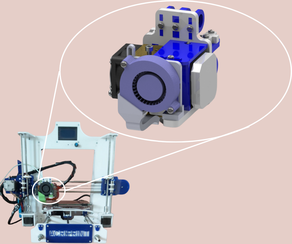
Fig.7
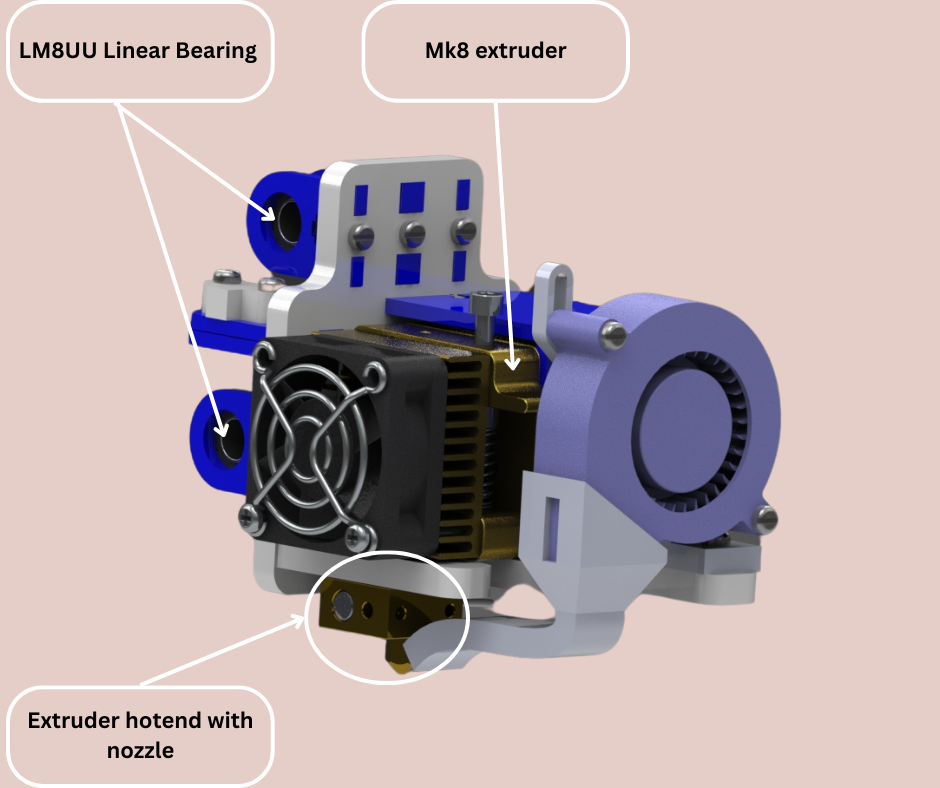
Fig.8
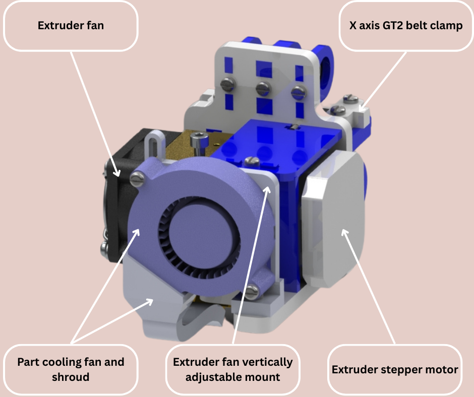
Fig.9
The extruder assembly is mounted to the X axis linear rods as shown in Fig.7. The extruder assembly is shown in more detail in Fig.8 and Fig.9. The extruder assembly features three lm8uu linear bearings held in place with acrylic clips. The extruder assembly is made to move by the X axis stepper motor using a GT2 timing belt. Since the belt is not a closed loop the extruder assembly has belt clamps (Fig.9) to clamp down on the free ends of the X axis timing belt. The assembly also has an adjustable mount for the parts cooling fan and shroud. This mount allows vertical adjustment of the parts cooling fan to align it with the extruder nozzle. The MK8 style extruder used in our extruder assembly is shown in Fig.10 with all the components labeled.
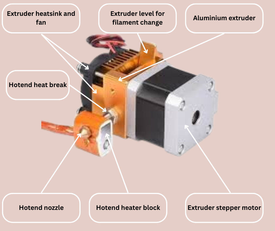
Fig.10
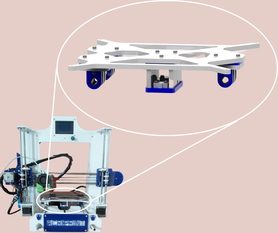
Fig.11
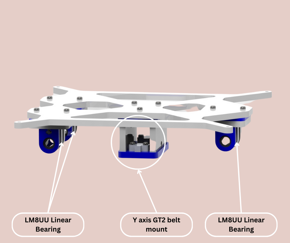
Fig.12
The Y axis bed assembly shown in Fig.11 is mounted to the two Y axis linear rods shown in Fig.3 using three lm8uu linear bearings shown in Fig.12. The bed assembly is made to move in the Y axis by the Y axis stepper motor using an open looped GT2 timing belt. The open ends of the belt are clamped using the belt clamps shown in Fig.12. As can be seen in Fig,13 the bed assembly features mounting points for a bed heater shown in Fig.14. Once attached to the bed assembly, a glass sheet measuring 20cmx20cm and 5mm thick can be clamped to the heater bed as shown in Fig.2. This glass surface will serve as the printing surface for the 3D printer.
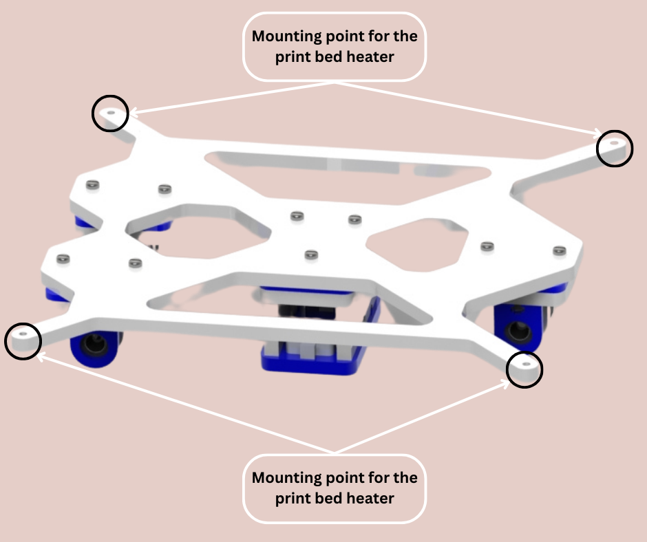
Fig.13
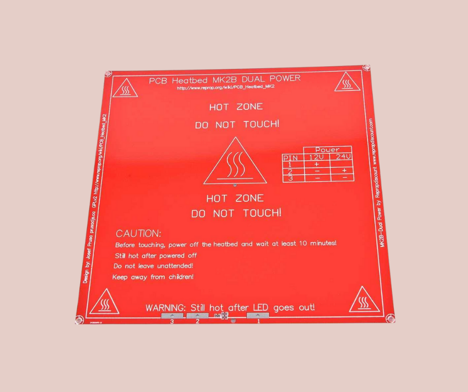
Fig.14
The rest of the construction was simply wiring, cable management and adjustments. At the first startup I ran a calibration sequence and 3D prints as mentioned in an excellent online guide by the Youtube Content Creator “Teachingtechyt”. After calibration one of the first 3D prints that this printer made was a shroud that I designed for the parts cooling fan shown in green in Fig.1. The shroud connects to the 5015 radial fan and redirects the air towards the part being printed. This cools down the filament after being deposited and prevents sagging of filament in overhangs. It improves the overall print quality. I have used this 3D Printer for more than one year and really put it through its paces. I have probably 3D printed more than five kilograms worth of plastic on this printer. While using this 3D Printer I made notes of all the aspects of the printer that could be improved and would be a requirement in the next version that I am going to design. The most important of these requirements are the following.
- More rigid frame of the 3D Printer
- Better limit switch mount for the Z axis. And Autobed levelling if possible
- Belt tensioners for the X and Y axis
- 3D Printed linear bearing mounts for all axes
- Better mounting location for the LCD
- Better cable management
- More print volume
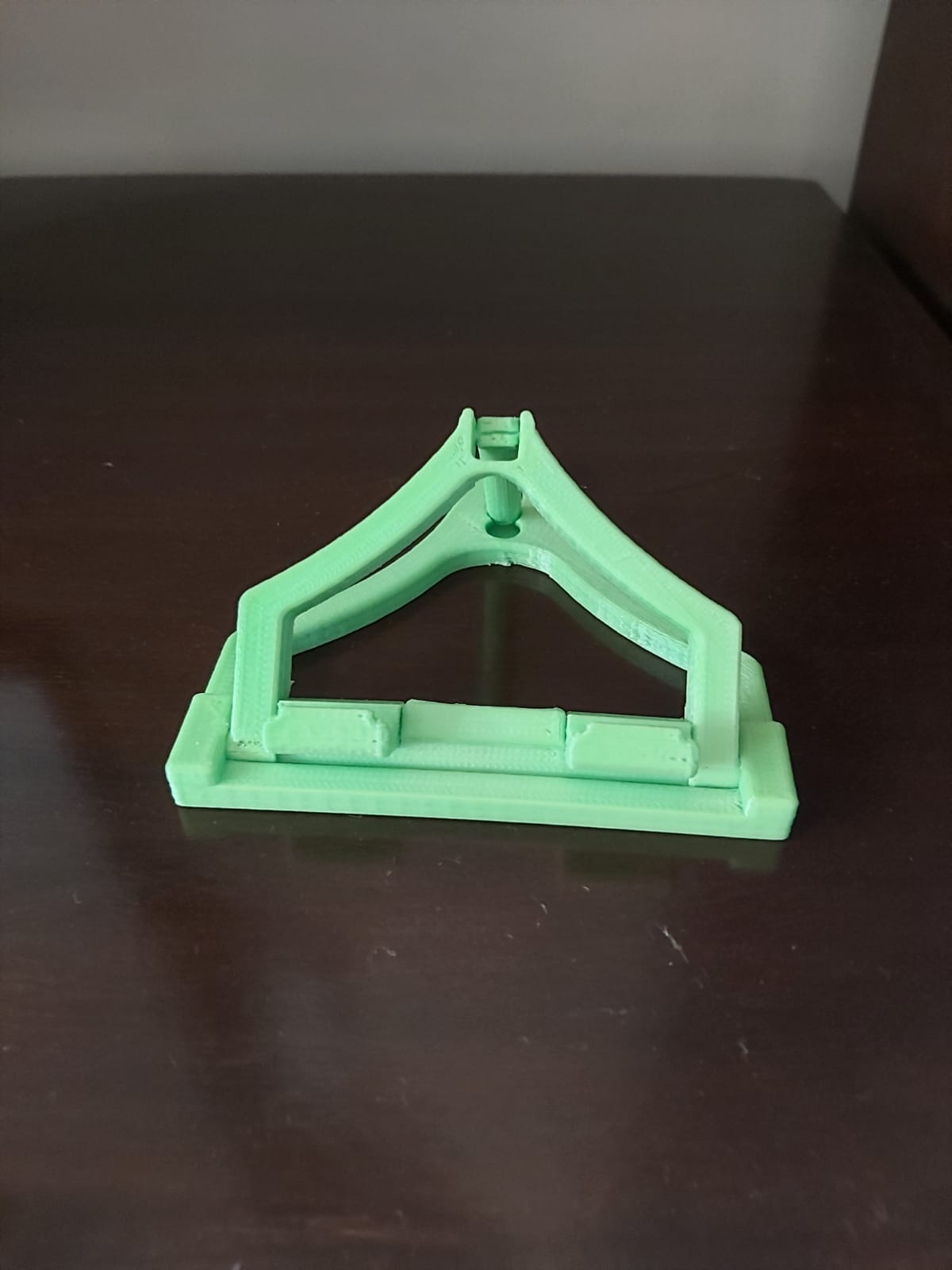
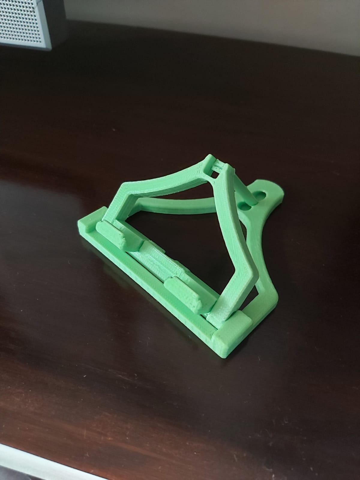
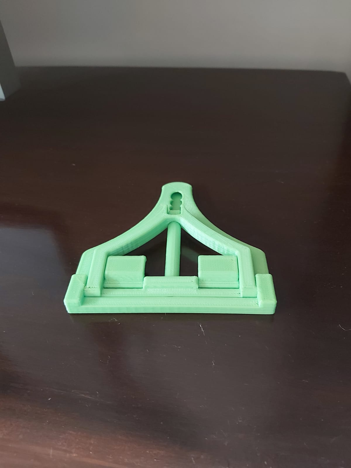
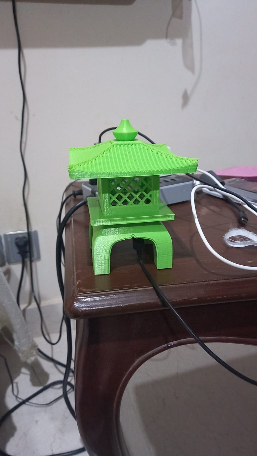
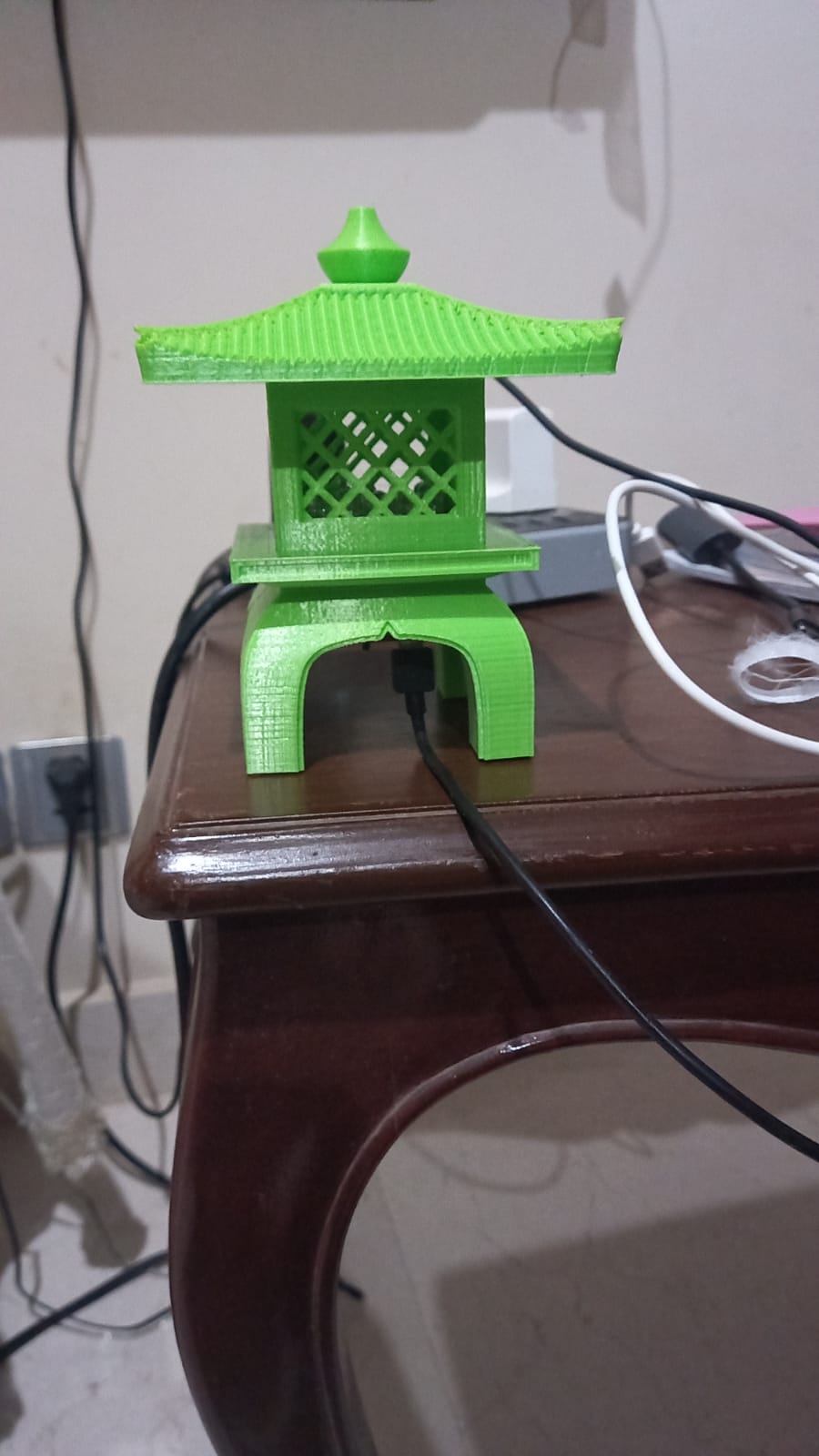
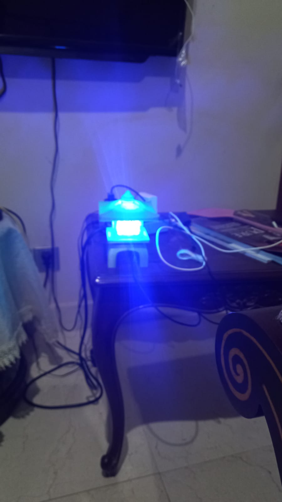
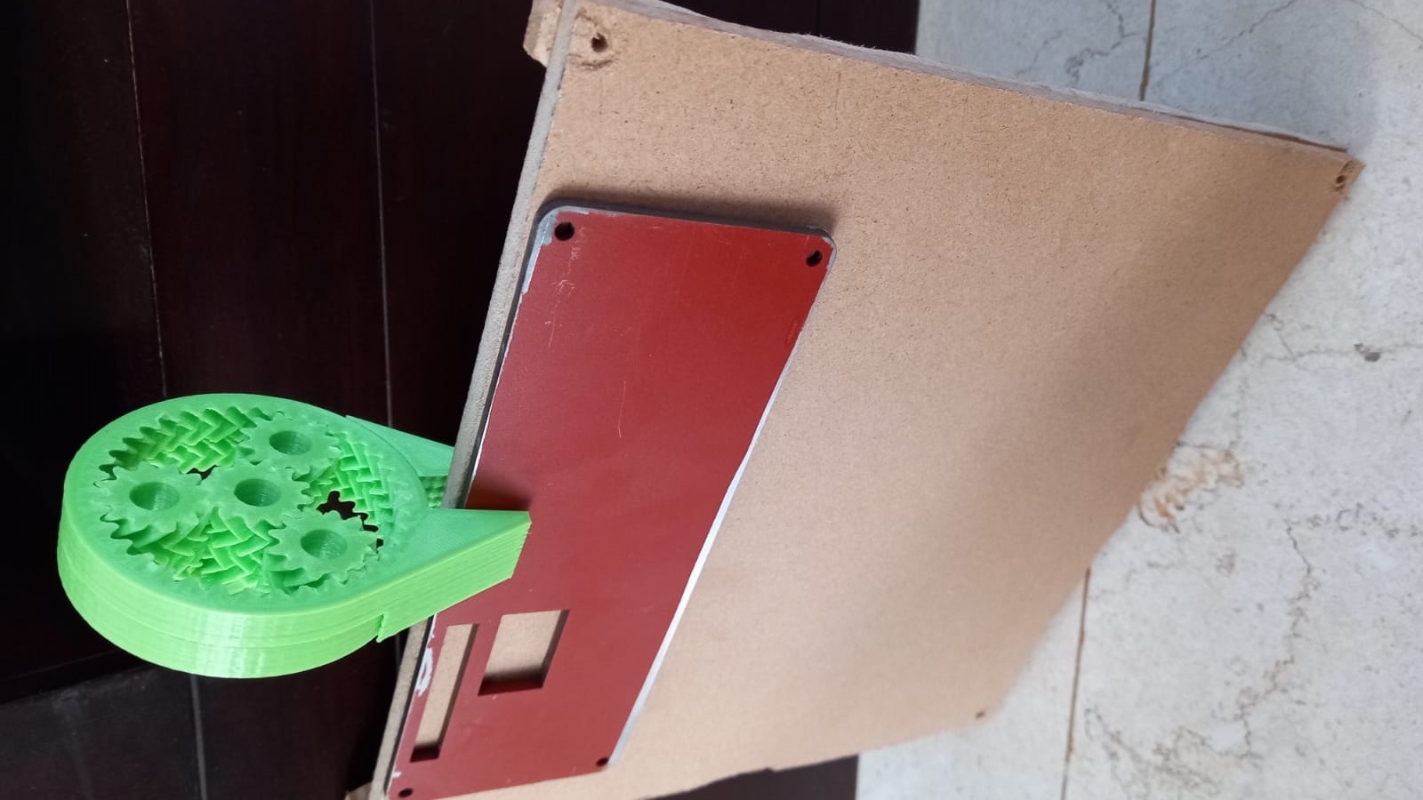
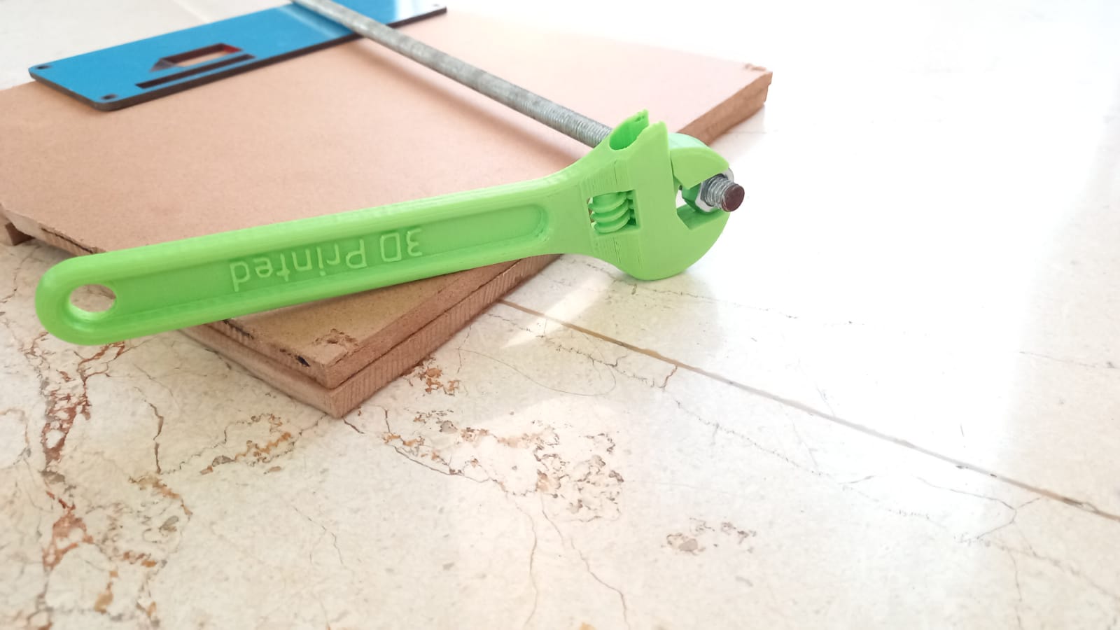
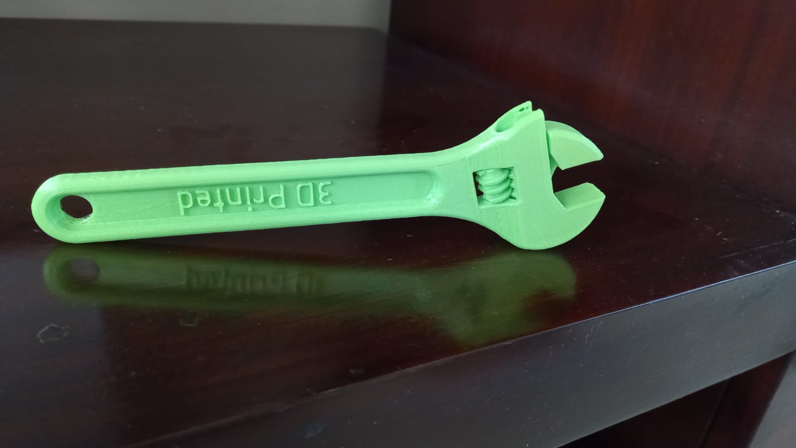
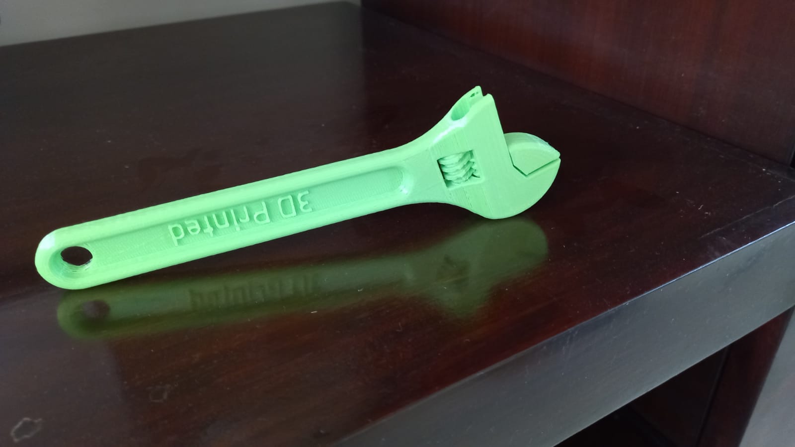
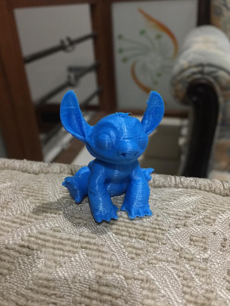
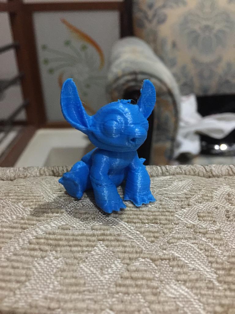
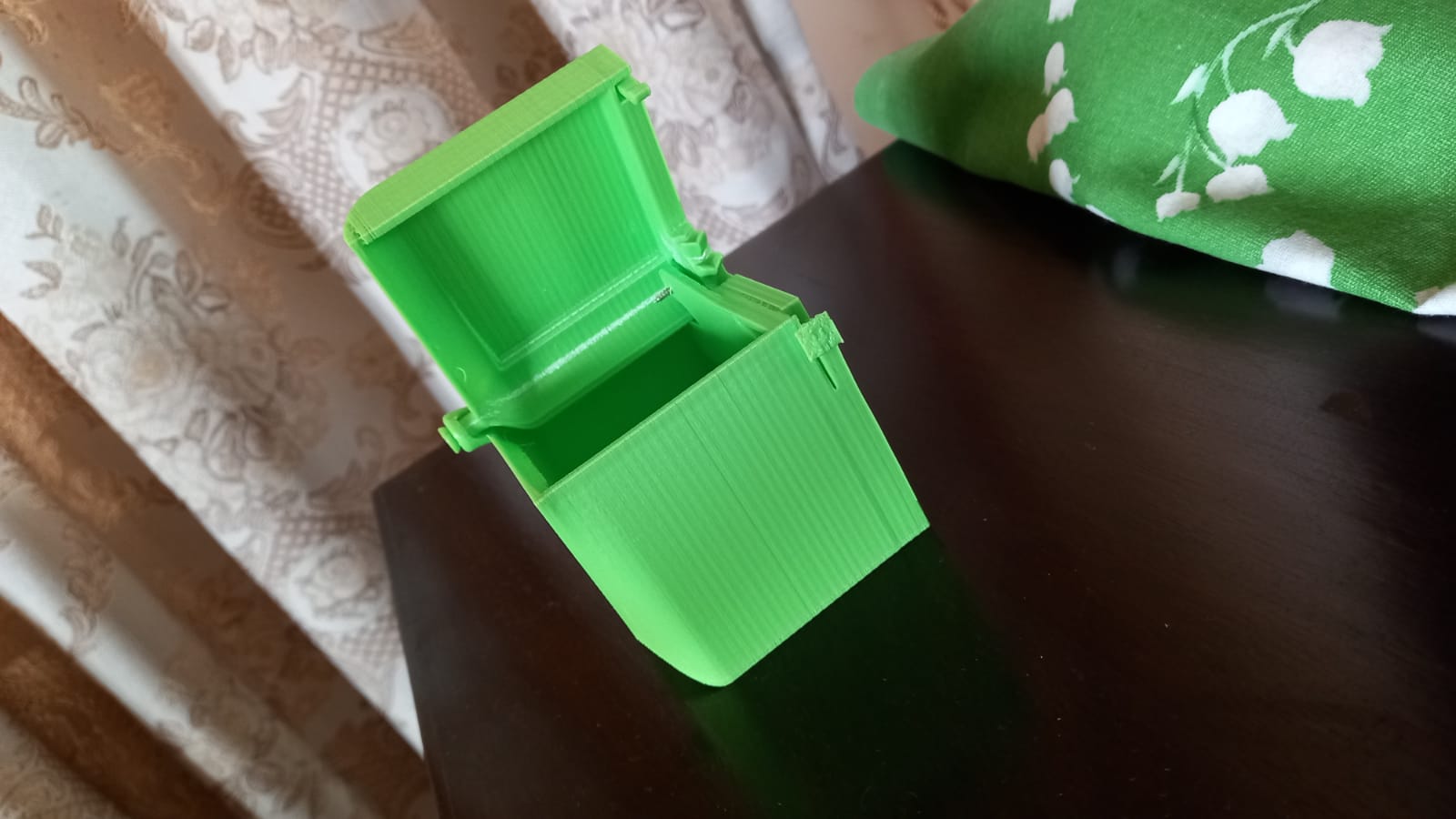
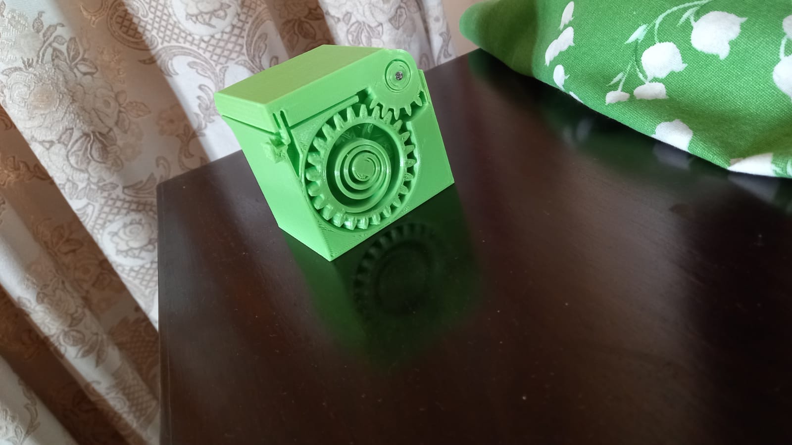
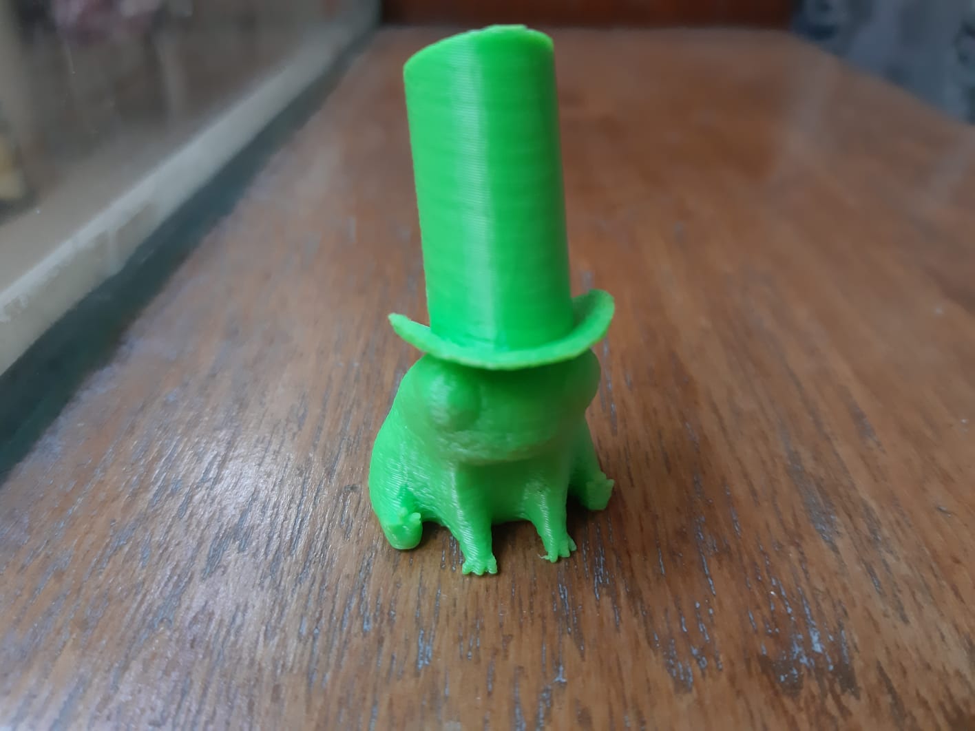
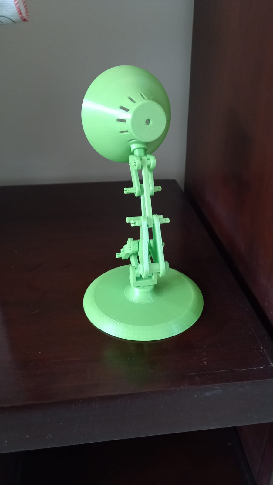
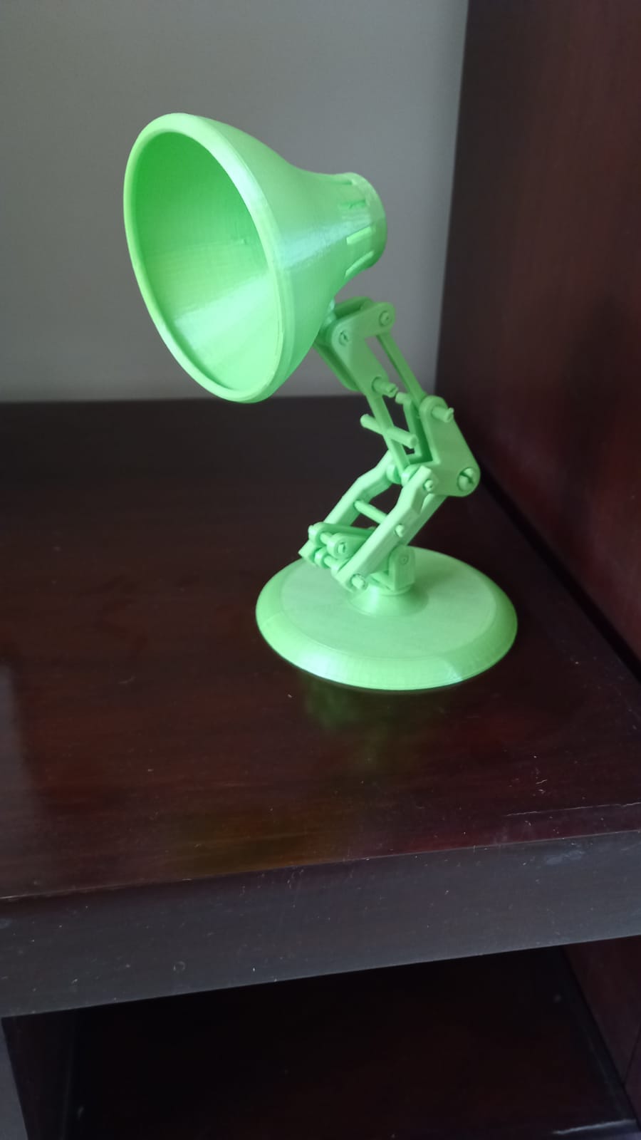
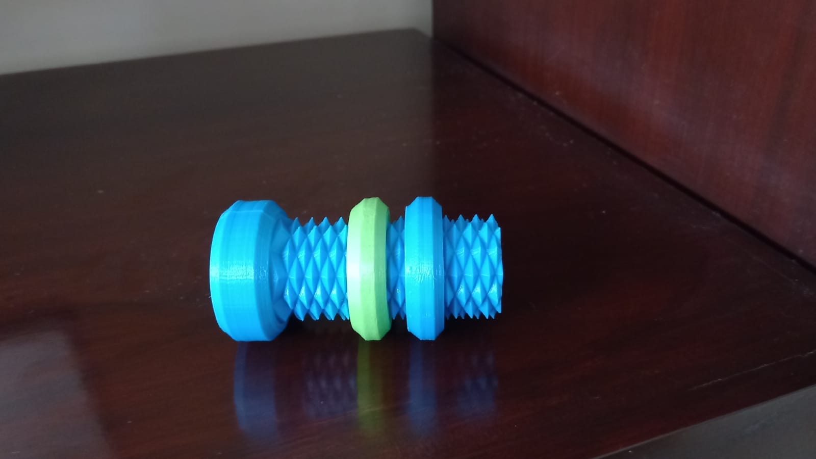
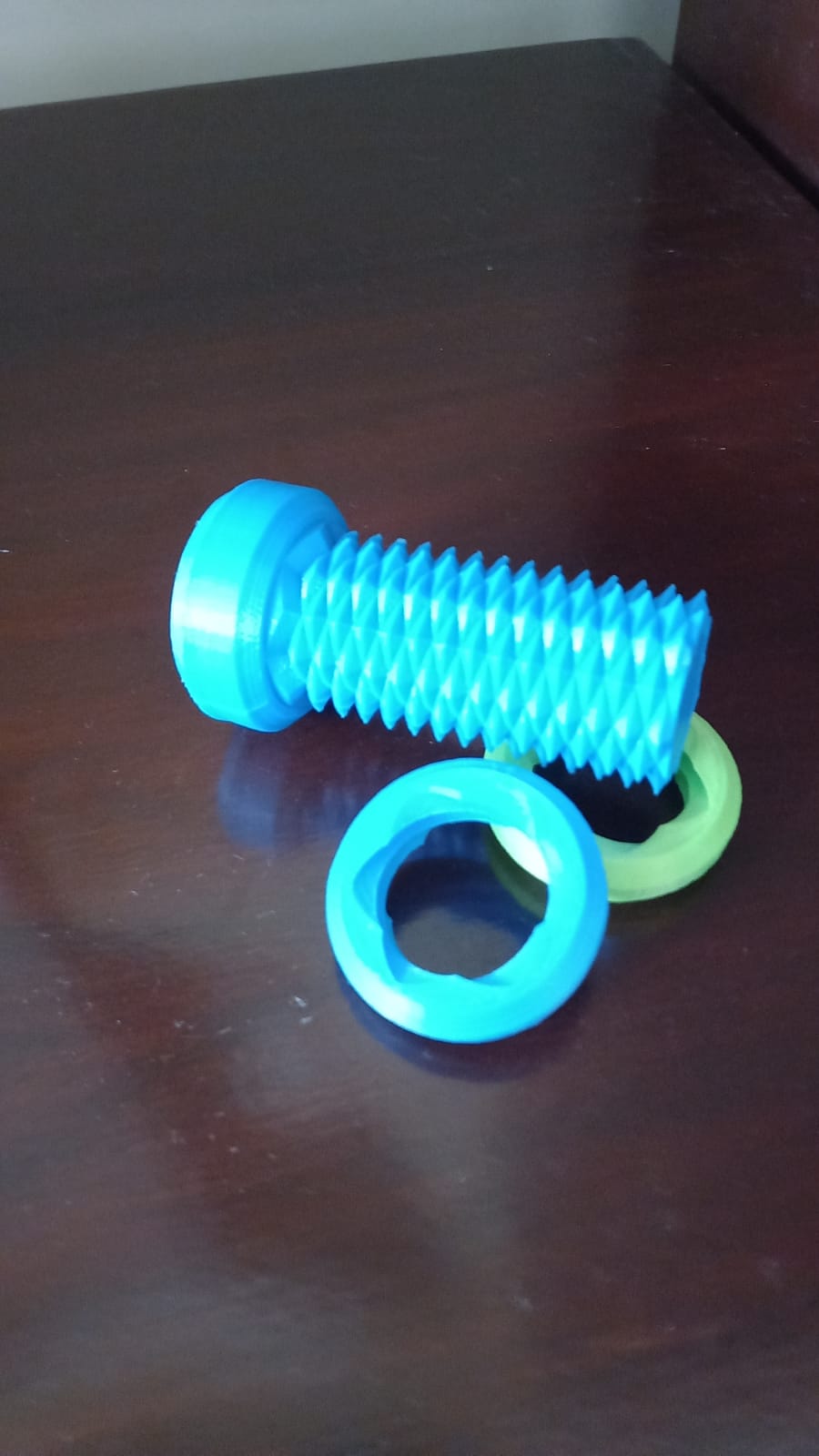
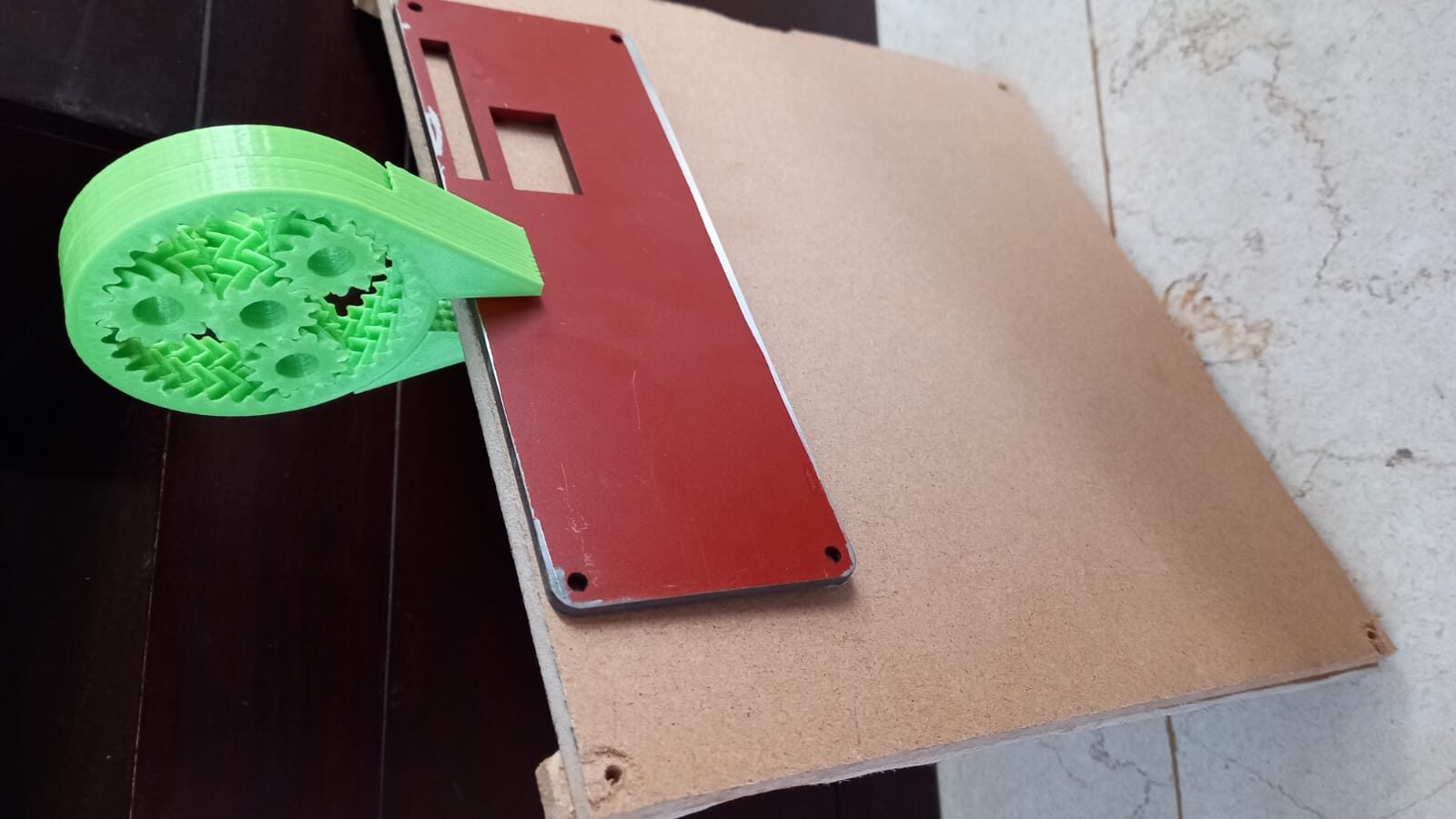
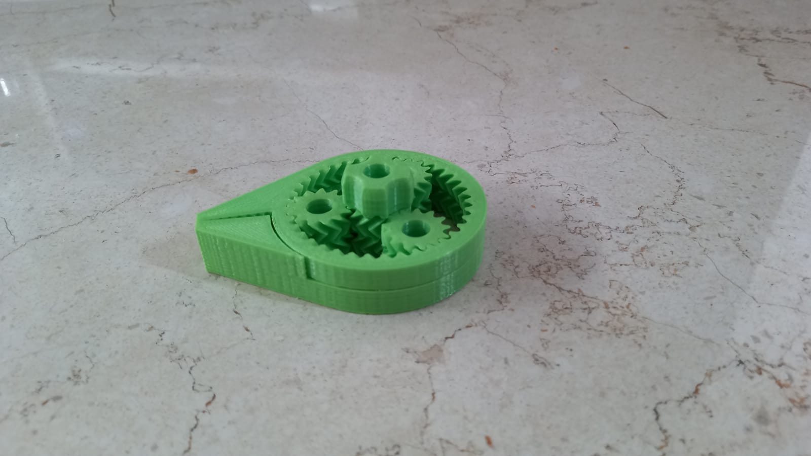
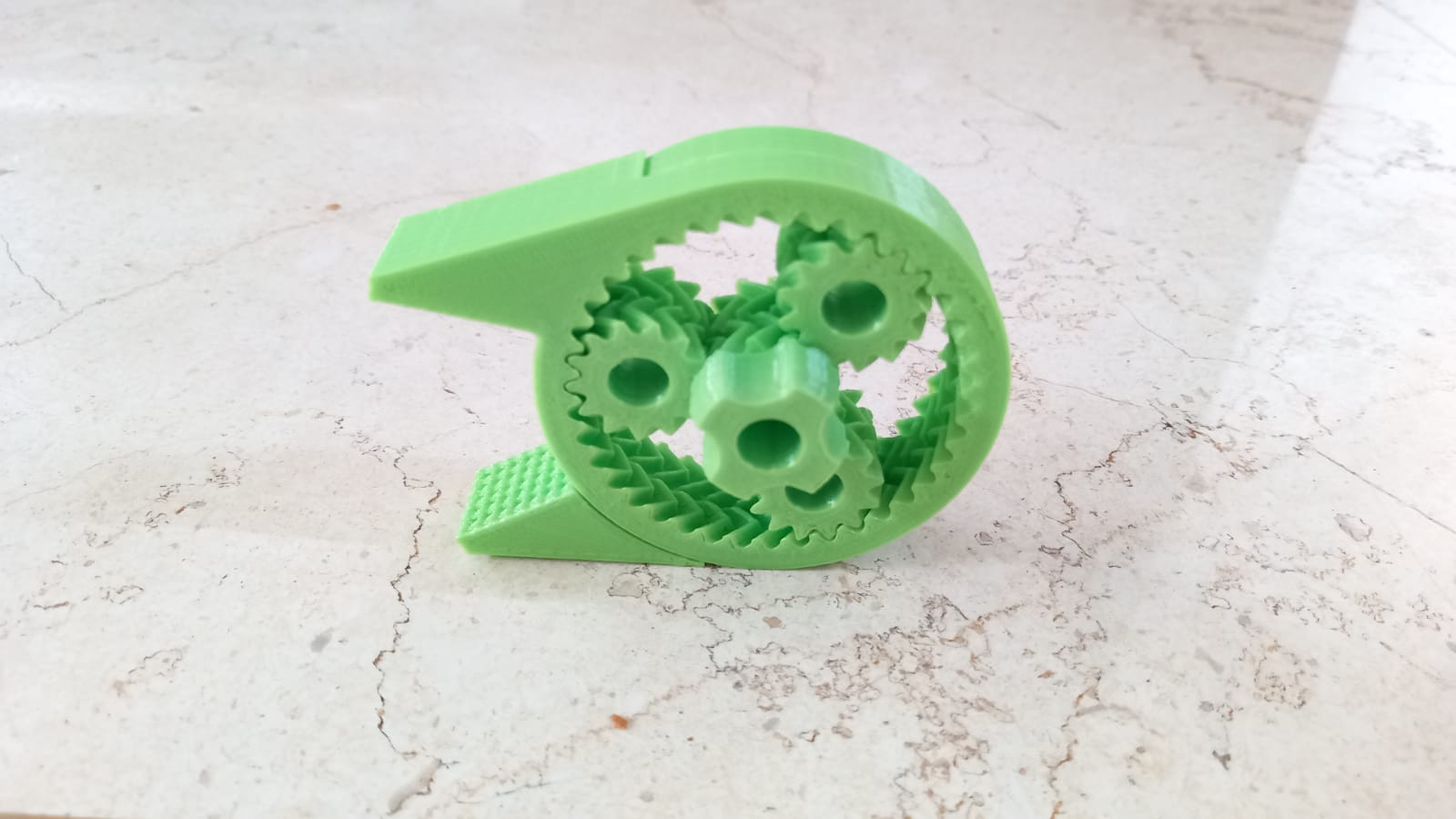
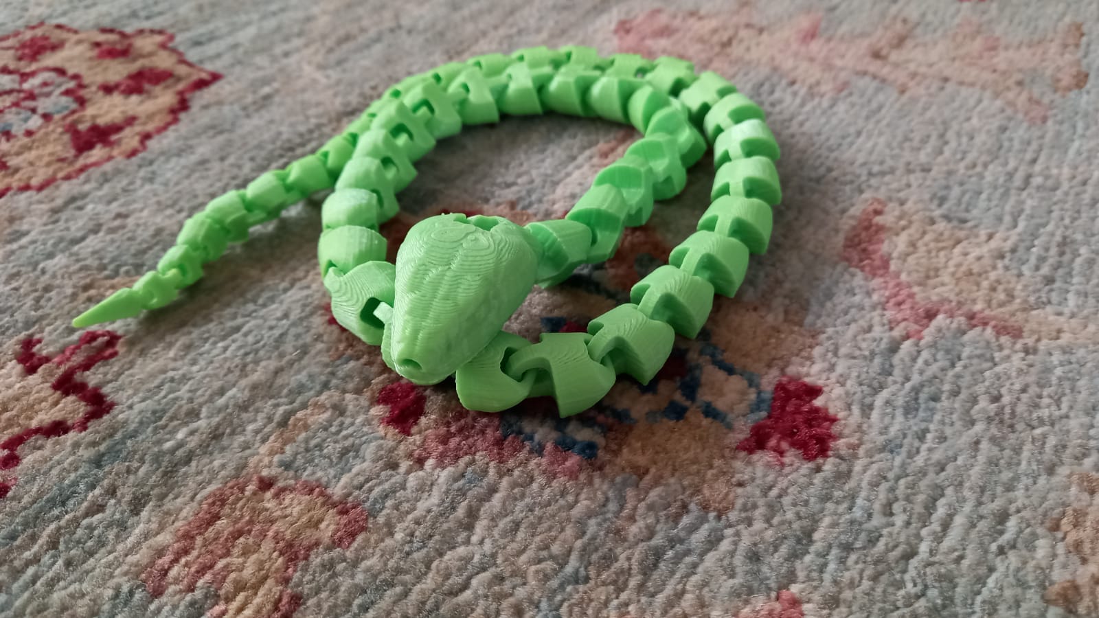
3D Printed Parts Gallery
The following images are of different open source designs 3D printed with the Acriprint version 1 3D printer.