As mentioned in my post titled “Prelude to my first 3D Printer: The Beginning”, before embarking on my rapid prototyping endeavors I was working on developing a small modular robotics platform as a learning tool for enthusiasts, hobbyists and students interested in programming, electronics and robotics. My idea was to develop it as a kit that can be assembled and programmed by the user. Since I did not have access to rapid prototyping tools at the time, I searched commercially for the hardware components and worked on developing the electronics and printed circuit boards.
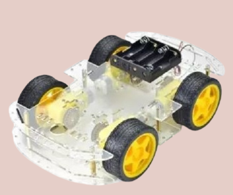
Fig.1
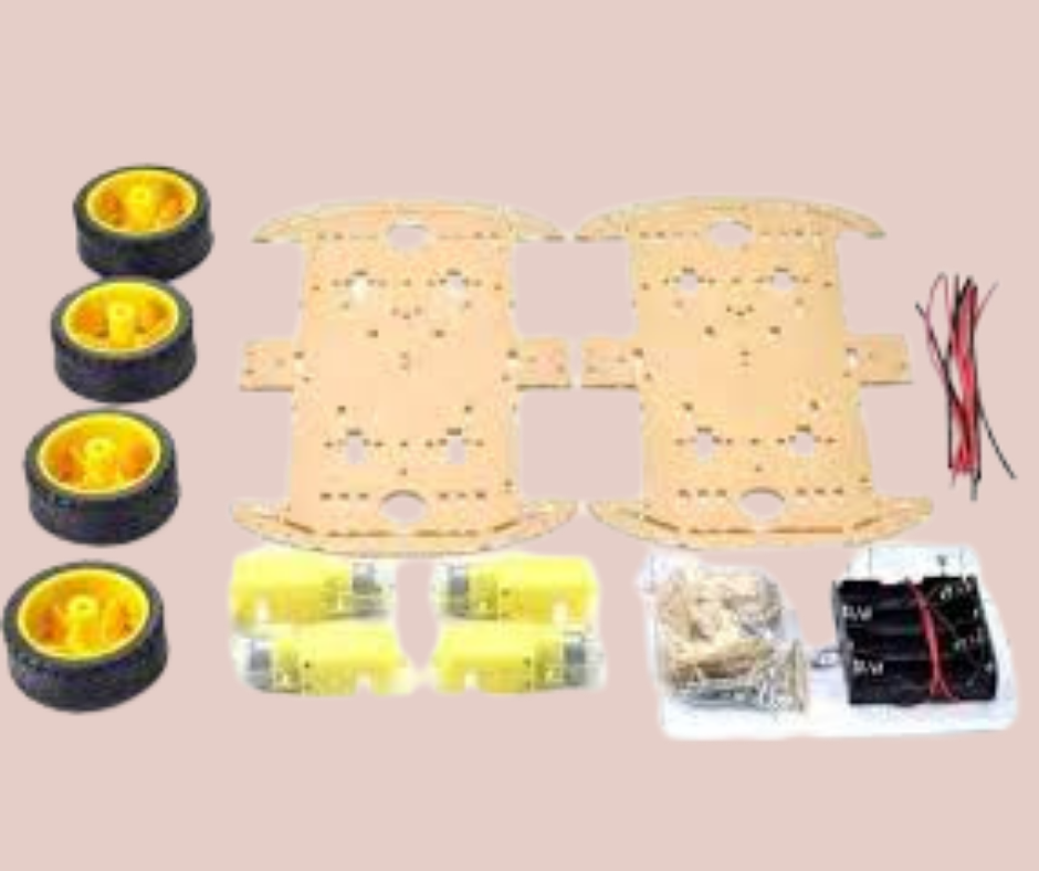
Fig.2
I found a commercially available four wheeled rover platform (Fig.1) that I liked. It consisted of laser cut acrylic parts (Fig.2) that needed to be joined together with provided bolts and nuts. The chassis also came with four geared DC motors and wheels that were connected to the chassis with provided bolts and nuts. One of the biggest reasons why I selected this chassis as a foundation for my project was that the chassis acrylic frame had many slots, holes and cutouts to attach accessories to. I wanted to use these as mounting locations for the electronics that I wanted to develop for it.
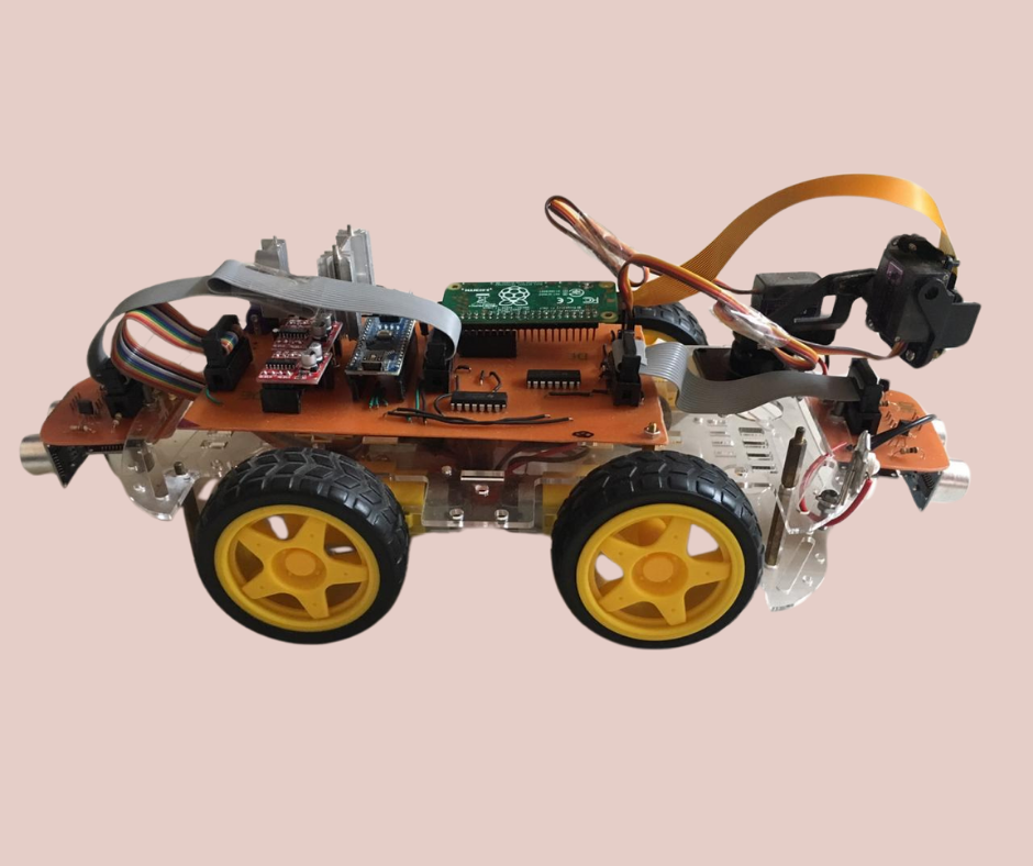
Fig.3
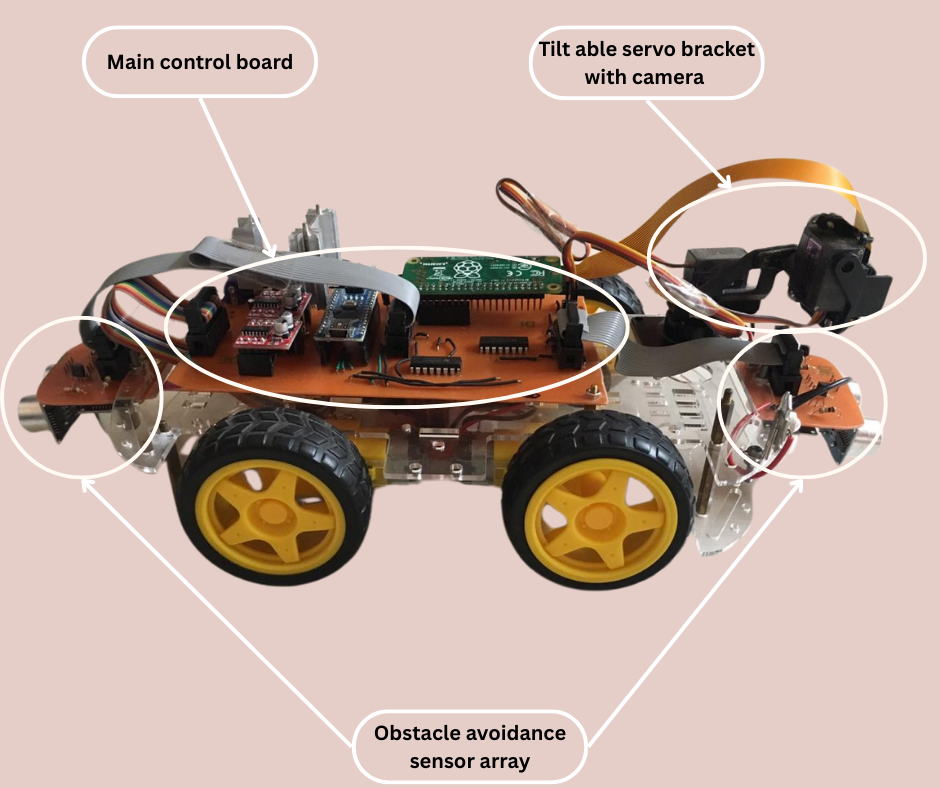
Fig.4
Fig.3 shows the first prototype that I developed using the rover chassis. As can be seen in the figure, the base chassis has been fitted with a number of electronic components that I wanted to integrate into my project and eventually into the robotics kit that I wanted to develop. Fig.4 has these main components labelled. We will now discuss these components individually.
Fig.5
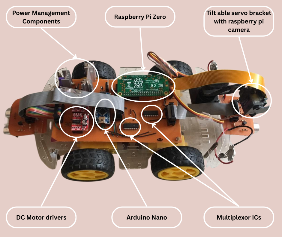
Fig.6
The main control board shown in more detail in Fig.5 and labelled in Fig.6 controls the entire rover. The main board has multiple voltage converters that take the 12V DC from the battery pack as input and output 3.3V, 5V and 6V DC. The main “brains” of the rover that handles all the communications, logic and controls is the Raspberry Pi Zero. It is a very scaled down version of the popular raspberry pi single board computer series. The Pi zero runs a lighter version of raspbian linux operating system. It has input and output ports as well as USB ports to control peripherals. As good as Raspberry Pi is at communications, processing, storage and algorithms, an arduino is much better at handling input, outputs, PWMs and interfacing with sensors. So to interface and control sensors and inputs and outputs, there is an arduino nano on the control board as well. To control the DC motors of the wheels of the rover there are two H-bridge DC motor controllers on the main board. These DC controllers get their PWM input from the arduino. PWM allows the speed of the DC motors to be controlled so that the rover speed can be increased or decreased. To increase the number of inputs to allow more for sensor capabilities, two multiplexor ICs are also included on the main board. These ICs essentially multiples the number of input and outputs of the arduino allowing interfacing with more sensors.
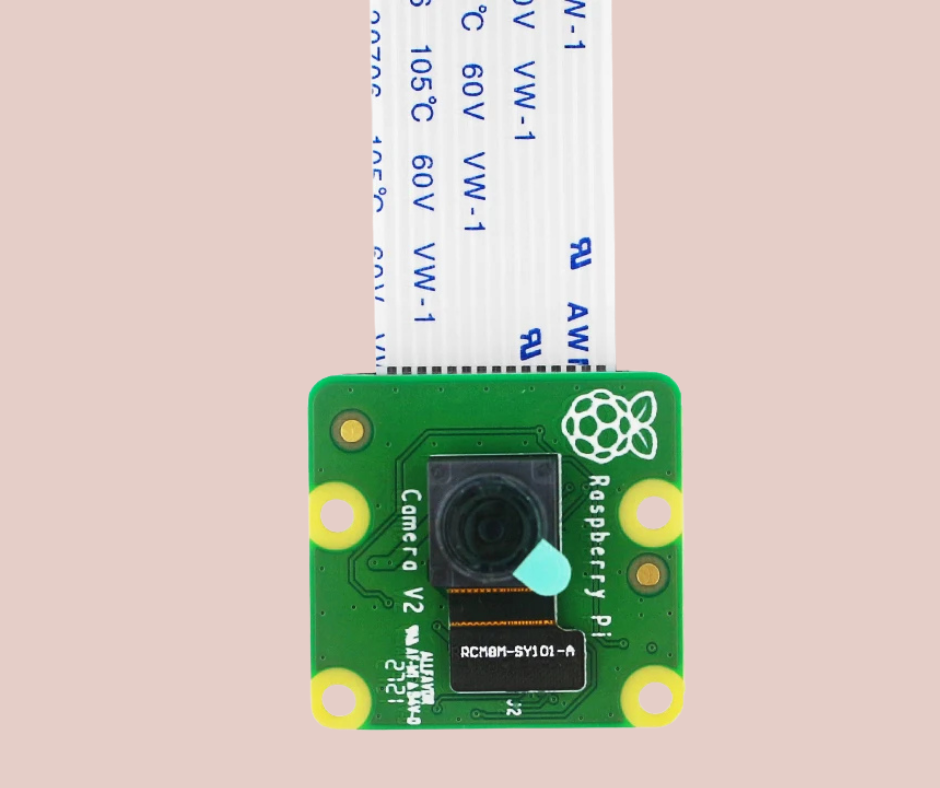
Fig.7
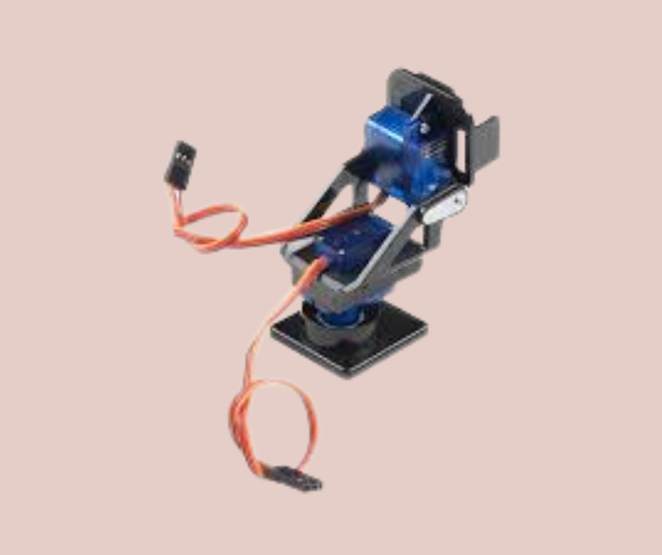
Fig.8
To add visual input capability to the rover, I added a camera as well. Specifically the raspberry pi camera shown in Fig.7. Although we can use any usb camera, I chose the raspberry pi camera because it is natively compatible with the Pi zero. To control the pan and tilt of the camera I mounted the camera on a pan and tilt bracket shown in Fig.8. This bracket has two servo motors that can accurately control the pan and tilt of the bracket. The camera with the bracket and servo motors is mounted top front of the rover as shown in Fig.3. The inputs to the bracket servos comes from the arduino nano because it has accurate and reliable PWM capabilities. The arduino essentially gathers all the information from all the sensors and relays that to the raspberry pi which then processes that information along with the data from the camera. The raspberry pi then sends control commands to the arduino which in turn executes those commands by controlling the motors and actuators.
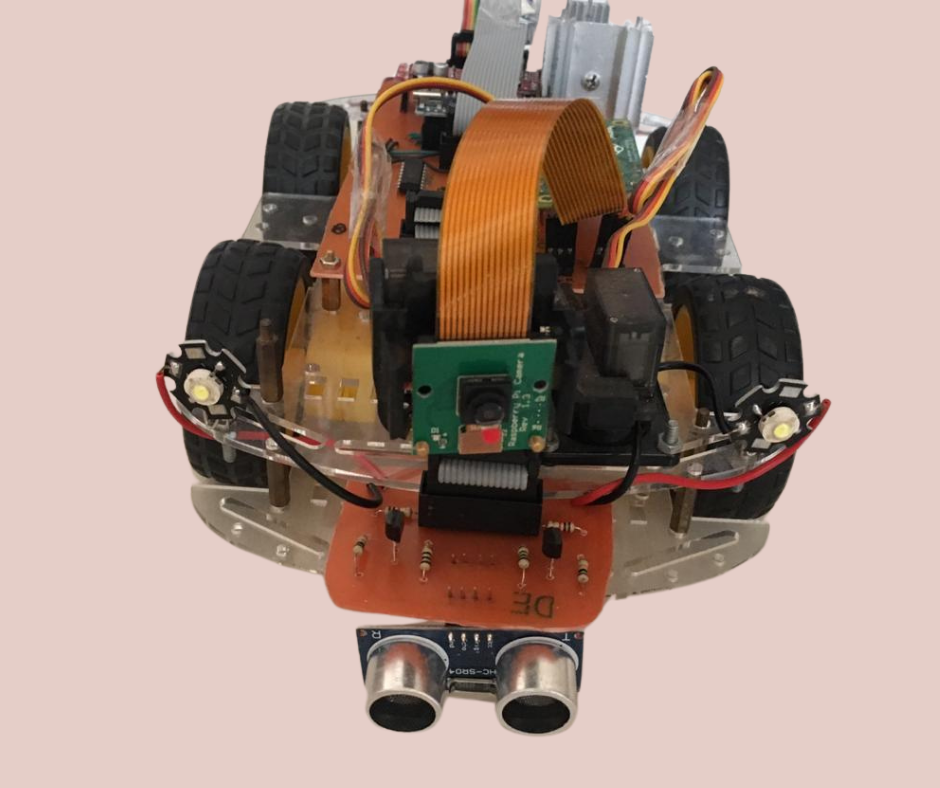
Fig.9
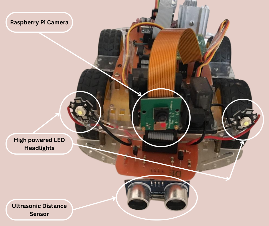
Fig.10
In addition to the main control board there are two peripheral sensor array boards as shown in Fig.4. These boards are for the obstacle avoidance aspect of the rover. This board is shown in more detail in Fig.9 and labelled in Fig.10. This peripheral sensor board has an ultrasonic sensor installed on it. This sensor uses ultrasonic waves to measure the distance from it to an object in front of it. This information can be used by the rover for obstacle avoidance and terrain mapping. This board also has an ultrasonic sensor on the underside to measure the distance from the board to the ground surface. This information can be used to prevent the rover from going over a ledge. The board also has multiple BJT transistors that can be used as switches to turn on and off additional components connected to it. For example the front sensor array has two high power LED headlights connected to it as shown in Fig.10. These lights can be switched on or off by a sending control signal from the main control board to the front sensor board. These peripheral boards are connected to the main control board using IDC connectors and ribbon cables.
I had also begun work on more such peripheral boards with different sensors to add more capabilities to this rover. This was when I began to focus on the aesthetic aspect of the rover. I wanted to enclose these bare electronic boards in custom designed enclosures that would complement the overall design of the rover. This lead me on a different adventure that I discussed in my post titled “Prelude to my first 3D Printer: The Beginning”.
Now we will talk about the functionality and testing of this rover. Unfortunately the video of the working of the rover got lost. But I will describe the best I can. To control the rover I set up a server on the raspberry pi zero on the rover. The server connected to my home WiFi network and would wait for an incoming connection. I then wrote a python program on my laptop that connected to the server running on the rover. My program then began receiving a video stream from the camera on the rover. I could send control commands from my laptop via the python program to the raspberry pi zero on the rover. The raspberry pi interpreted my commands and after applying its logic, the pi sent commands to the arduino to control the motors and actuators. This way I could control the rover over WiFi while also being able to see what the rover camera was seeing. The rover sensors were also testing by seeing if it could detect obstacles or ledges which it could. This result opened a lot of very interesting, fun and exciting capabilities when it came to designing algorithms for the rover.