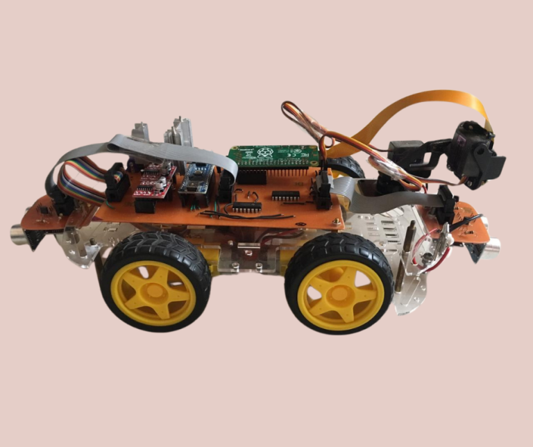
I have always loved remote controlled toys. I remember watching “home alone 3” when I was little and getting really excited when a handheld camera is duct taped to the RC car and this makeshift car drone is used to spy on the bad guys. This movie scene is still clear and vivid in my mind to this day. This was one of the reasons why I developed the earlier robotic rover that I talked about in my project post titled “IoT enabled Robotic Rover as a STEM learning tool”. That four wheeled rover also had a camera installed on it and could be controlled remotely. But one of the biggest shortcomings of that rover was its very limited ground clearance. This meant that if it encountered any step with a height larger than 15-20 mm, then it would fail to go over it. This meant that it was unsuitable and not drive-able over uneven terrain like in gardens or fields.
So I began looking for a different commercially available robotics chassis to transfer my existing electronics and sensor arrays to. My selection criteria was the following.
- Have good ground clearance
- Have mounting points for electronics and sensors
- Chassis design should cater to driving over uneven terrain
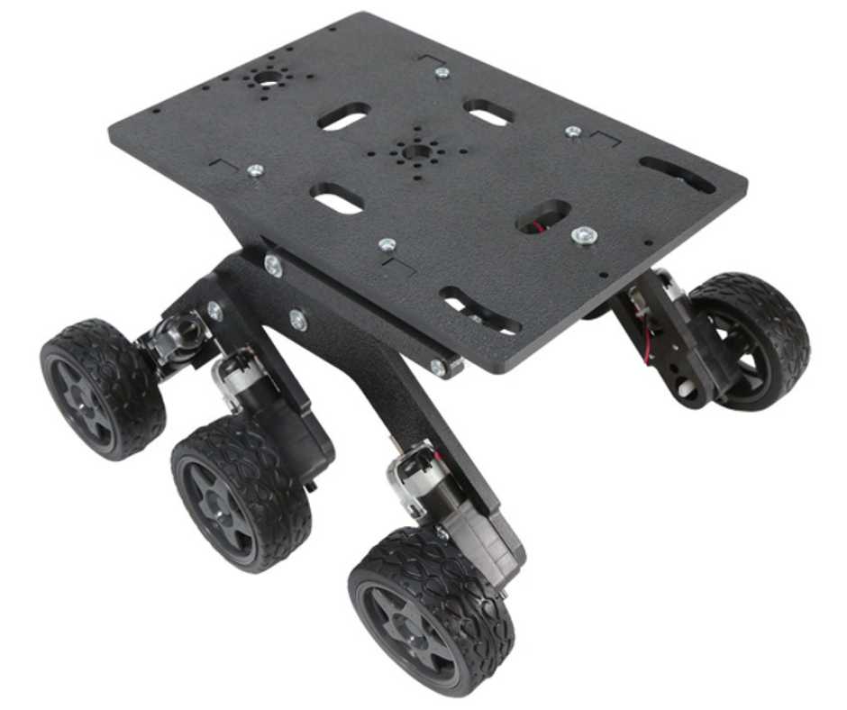
Fig.1
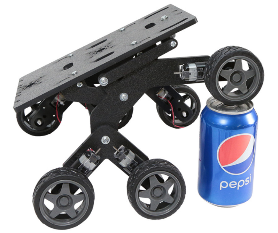
Fig.2
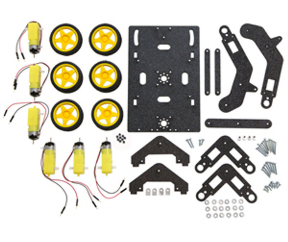
Fig.3
I was able to find a robotics chassis by “servocity.com” shown in Fig.1 and Fig.2 that seemed to fit these basic requirements. This robotics chassis consists of laser cut acrylic parts that come in the form of a kit that has to be assembled by the user as shown in Fig.3.
Fig.4
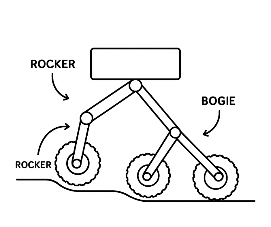
Fig.5
This rover design employed a version of the rocker bogie suspension system designed by NASA for the rovers sent to mars for exploration. This suspension system is shown in Fig.4 and Fig.5 and is designed specifically for use on uneven rugged terrain and ideal for clearing obstacles. The system consists of the following.
- Rocker: A large, pivoting arm on each side of the rover that “rocks” up and down.
- Bogie: A smaller pivoted link attached to the rocker, holding two wheels.
- No springs: Instead of traditional springs or shocks, the system relies on mechanical linkages for stability.
When one wheel encounters an obstacle (like a rock), the system allows it to rise over it while keeping the other wheels on the ground, maintaining traction. The load is distributed across all wheels, reducing the risk of tipping or getting stuck. It allows rovers to climb over obstacles up to twice the wheel diameter while keeping the chassis relatively stable. The main rover carriage is kept stable and prevented from tipping by the differential system of linkages shown in Fig.6.
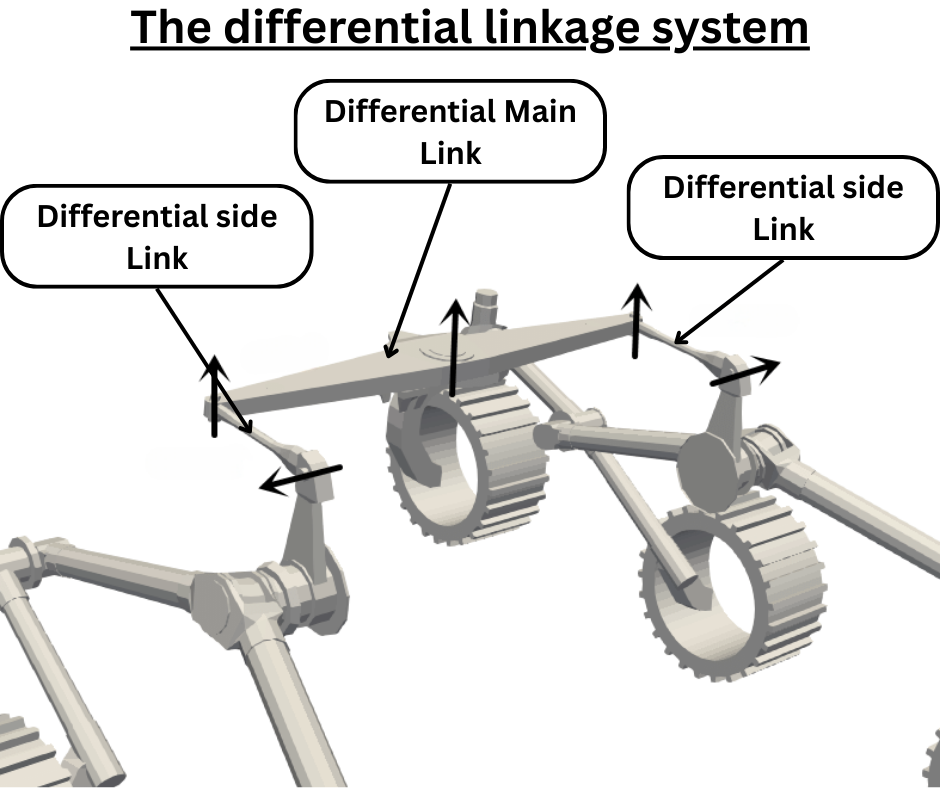
Fig.6
So I ordered the kit from “servocity.com” and assembled it when it arrived and tested it out. The design worked well as advertised and it was able to traverse over obstacles that had heights of more than half the diameter of the rover wheels. But there were some issues that made me rethink about using that chassis as a foundation for my new rover design. These issues were as follows.
- The motors that this rover chassis used were not powerful enough. If the rover encountered any step or obstacle with height larger than half the diameter of the rover wheel, the motors would stall
- The rover had no steering. This meant that it used tank steering to turn. This was fine on level and hard ground. But it was not possible on rough, uneven and soft ground.
- The frame of the rover was not rigid enough because the acrylic panels were only 6mm thick. Placing any load on the rover frame caused the panels to bend.
- The parts of panels that were involved in rotation did not use bearings. There was plastic on plastic contact that caused friction especially when under load.
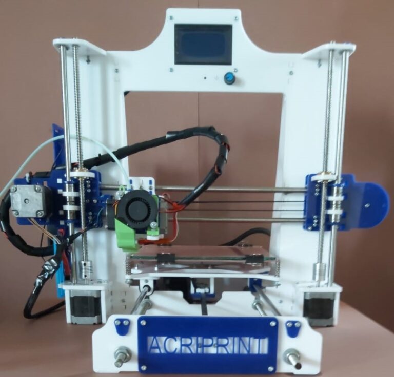
For these reasons and more, I decided to design and manufacture a more rigid and robust rover with steering that would be capable of traversing over rough and uneven terrain. For this project I decided to use both laser cutting and 3D printing. I decided to use laser cut acrylic panels for the large structural components of the rover frame because of two main reasons. Firstly my 3D printer only had a printing volume of 20cmx20cmx20cm. Printing large structural components would require printing in sections which would take an enormous amount of time. Secondly the cost of laser cutting the large panels would be a fraction of the cost if the large parts were to be 3D printed. My idea was to laser cut all the large pieces and then combine them with 3D printed parts to make them rigid. Also all the bearing and motor mounts, mechanical and moving parts were to be 3D printed.
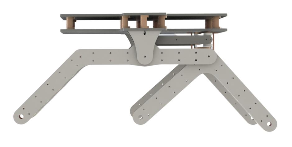
Fig.7
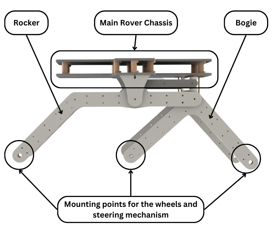
Fig.8
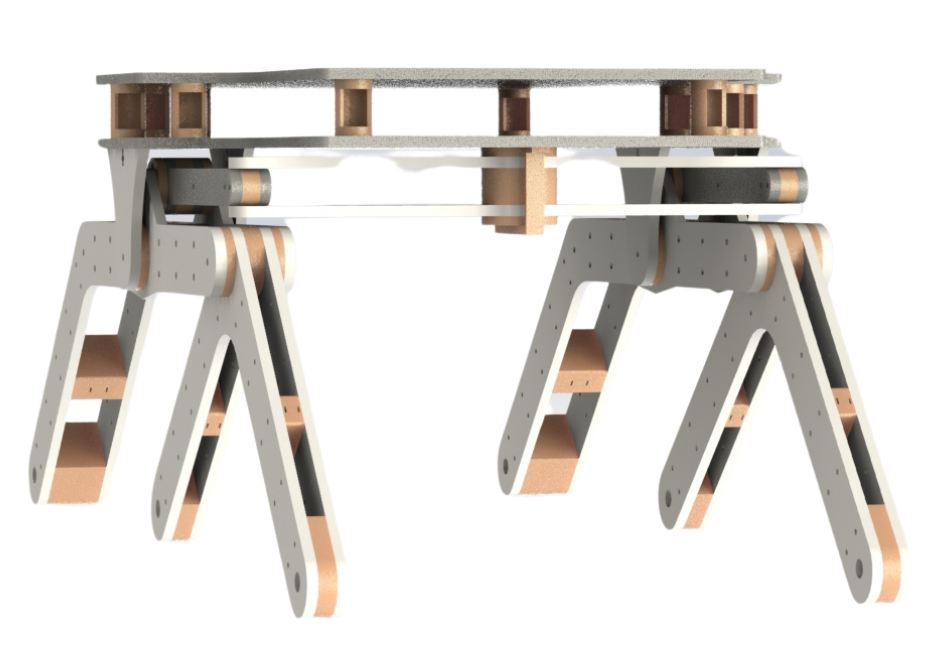
Fig.9
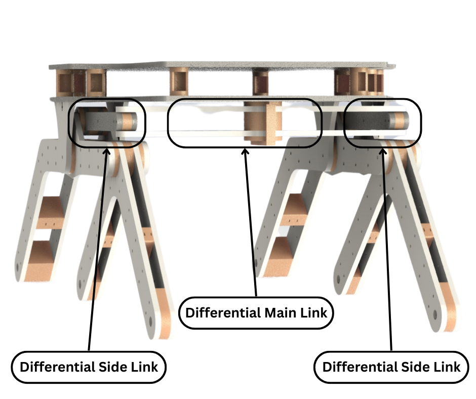
Fig.10
Fig.7 shows my rover chassis/frame design. I designed this using Solidworks. The design incorporates the Rocker bogie suspension system with a mechanical differential linkage system to stabilize the rover chassis. The rover consists of the main rover chassis which holds all the electronics, sensors and accessories. Then there are the rocker and bogie arms for each side. Then there is the differential linkage system to connect the two rocker bogie systems together. These different components are shown in Fig.8, Fig.9 and Fig.10.
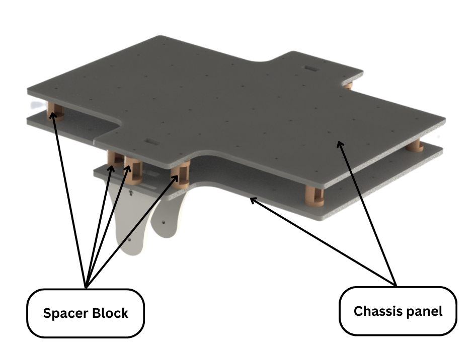
Fig.11
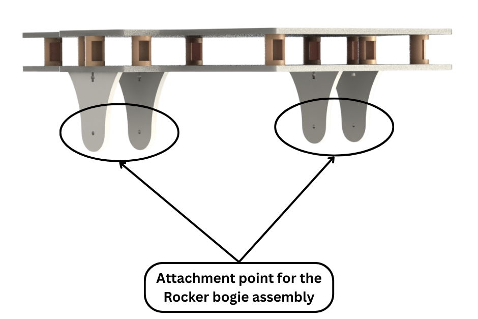
Fig.12
Fig.11 and Fig.12 show the main rover chassis clearly. This frame consists of two large laser cut 6mm thick acrylic panels joined together with multiple 3D printed spacer blocks. This forms a rigid and strong structural frame that will not bend under load. The two large panels also have multiple 3mm holes cut into them to provide attachment points for electronics, sensors and other attachments. These holes are positioned in a pattern to make later designing easier. The two panels form two decks where electronics and accessories can be attached. The lower deck can be used purely for electronics and batteries while the upper deck can be used for attachments such as robotic arms or drones. The chassis frame also consists of smaller acrylic panels that when attached to the main frame provide attachment points for the two rocker bogie assemblies.
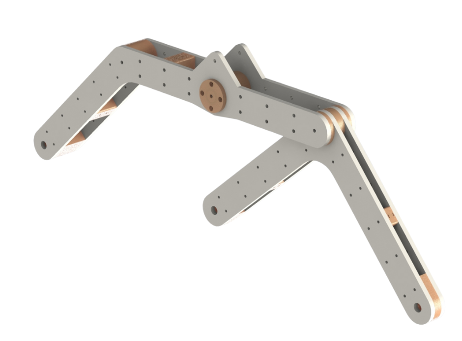
Fig.13
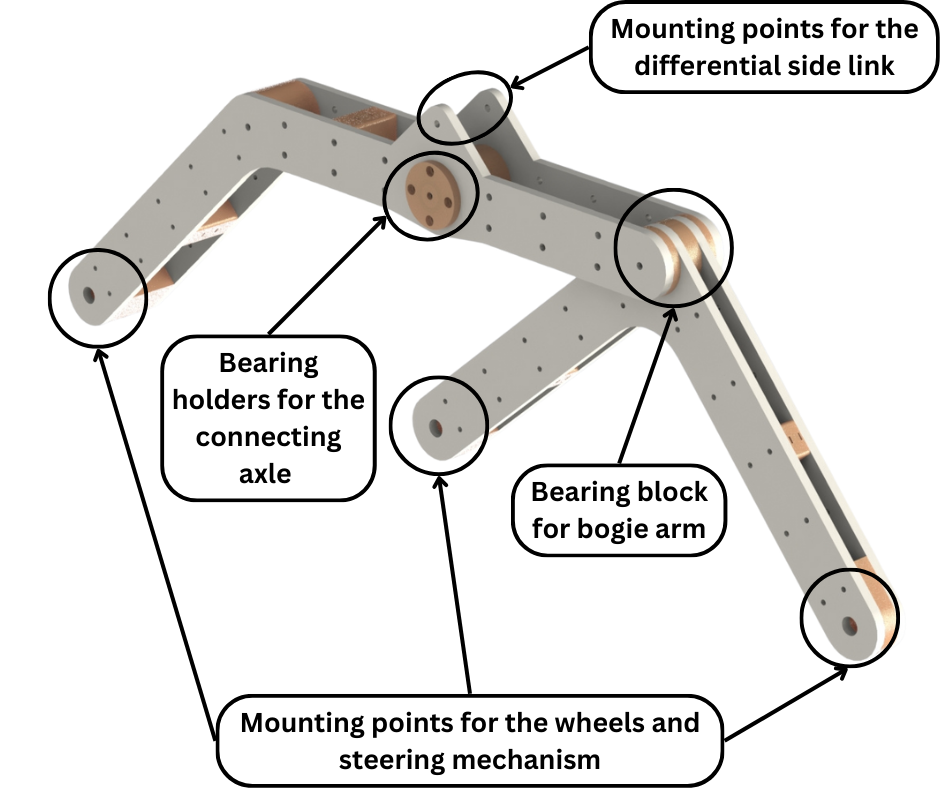
Fig.14
Fig.13 and Fig.14 show a rocker bogie assembly. Like the main chassis, both the rocker and the bogie structures consist of large laser cut acrylic panels joined together by 3D printed spacer blocks. The rocker arm assembly also has a bearing block to which the bogie arm assembly connects using a 4mm bolt as an axle. This bearing block allows the bogie arm to rotate freely about its axle. Both the rocker arm and the bogie arms have mounting points at their ends for the wheel and steering assemblies. The rocker bogie assembly also has mounting location for the differential side linkage as well. This rocker bogie assembly connects to the mounting point on the main chassis assembly using an 8mm threaded rod as an axle. To allow friction free rotation about its axle, the rocker bogie assembly has another bearing block at the center of the rocker arm.
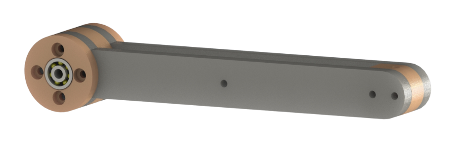
Fig.15
Fig.15 shows a side linkage assembly of the differential system. This connects to the rocker bogie assembly using a 4mm bolt as an axle. This also contains a bearing block to allow friction free rotation of the linkage.
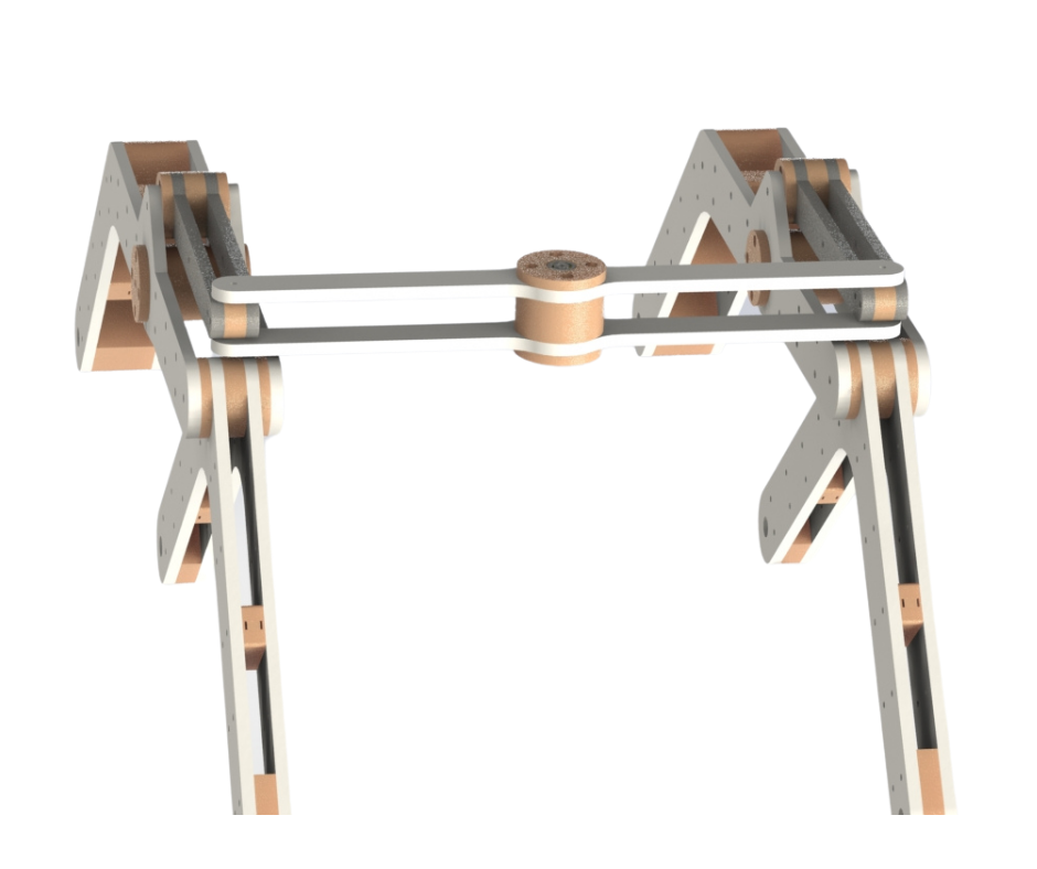
Fig.16
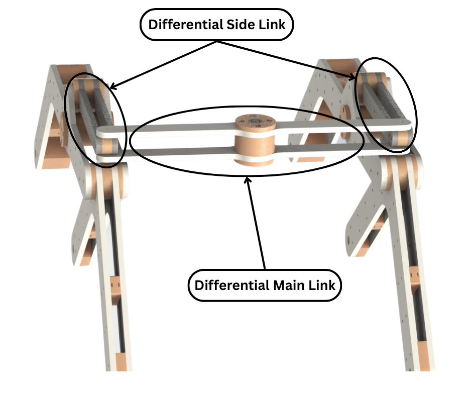
Fig.17
Fig.16 and Fig.17 show the two rocker bogie assemblies being connected together using the differential linkage system. This system consists of two side linkage assemblies and one main linkage assembly. All these differential linkages have bearing blocks to allow for friction free rotation.
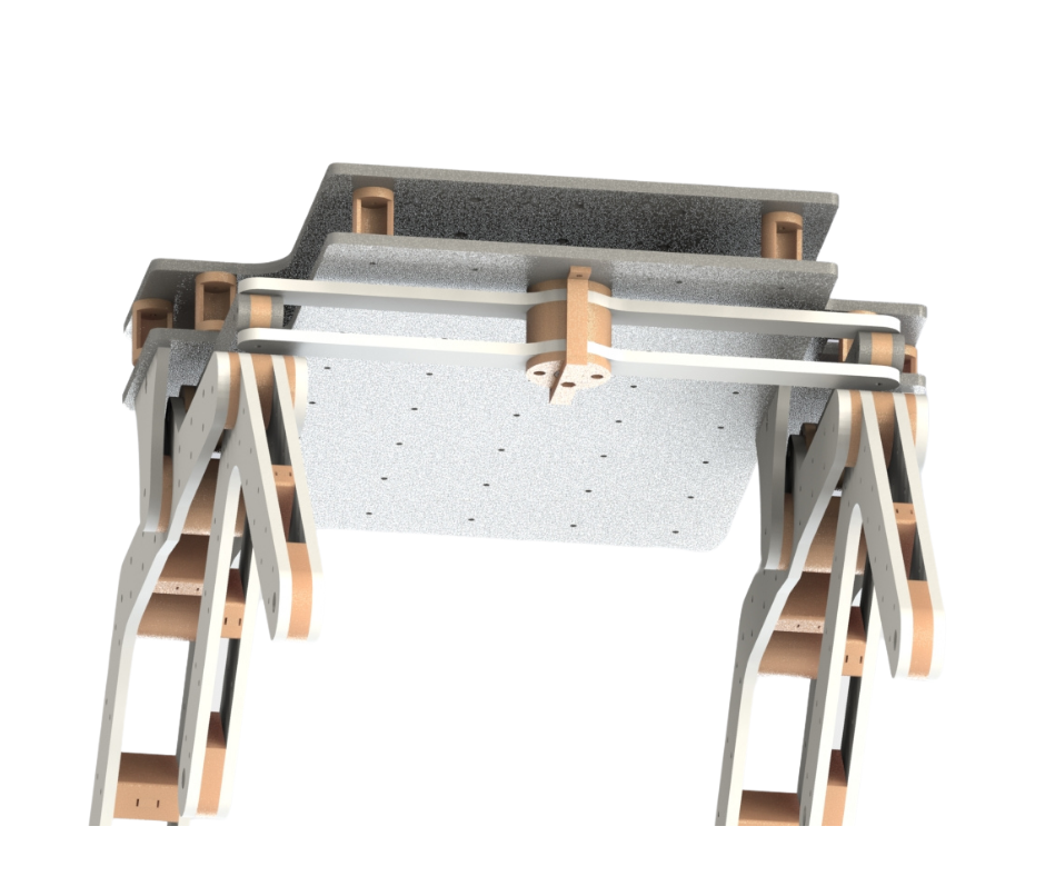
Fig.18
The main differential linkage assembly connects to the main chassis as shown in Fig.18. Combined together, this differential linkage system provides rigidity and stability to the main chassis when the rover traverses over uneven terrain and prevents the chassis from tipping over forwards or backwards. This differential system also ensures that all wheels of the rover are in contact with the ground surface at all times as shown in Fig.1.
In the next post about this rover, the wheel and steering assembly will be discussed.