This is our second post regarding our 6WD rover project. In our previous post we discussed our motivation for this project and we discussed in detail the design of the chassis/frame of our six wheeled rover. In this post we will wheel design and steering mechanism of our rover.
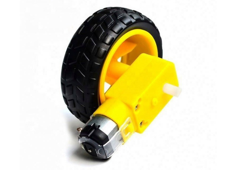
Fig.1
For this project we explored several different designs and mechanisms for adding steering capabilities to our rover. Initially we wanted to reuse the wheels and the motors (Fig.1) provided to us in the rover kit by “servocity” that we mentioned in our first post of this project. There were six wheels and motors in that kit. So when designing the wheel mount for our rover, we initially decided to design the mount around those wheels and motors in order to reuse them. We also had to design the steering mechanism into the wheel motor mount.
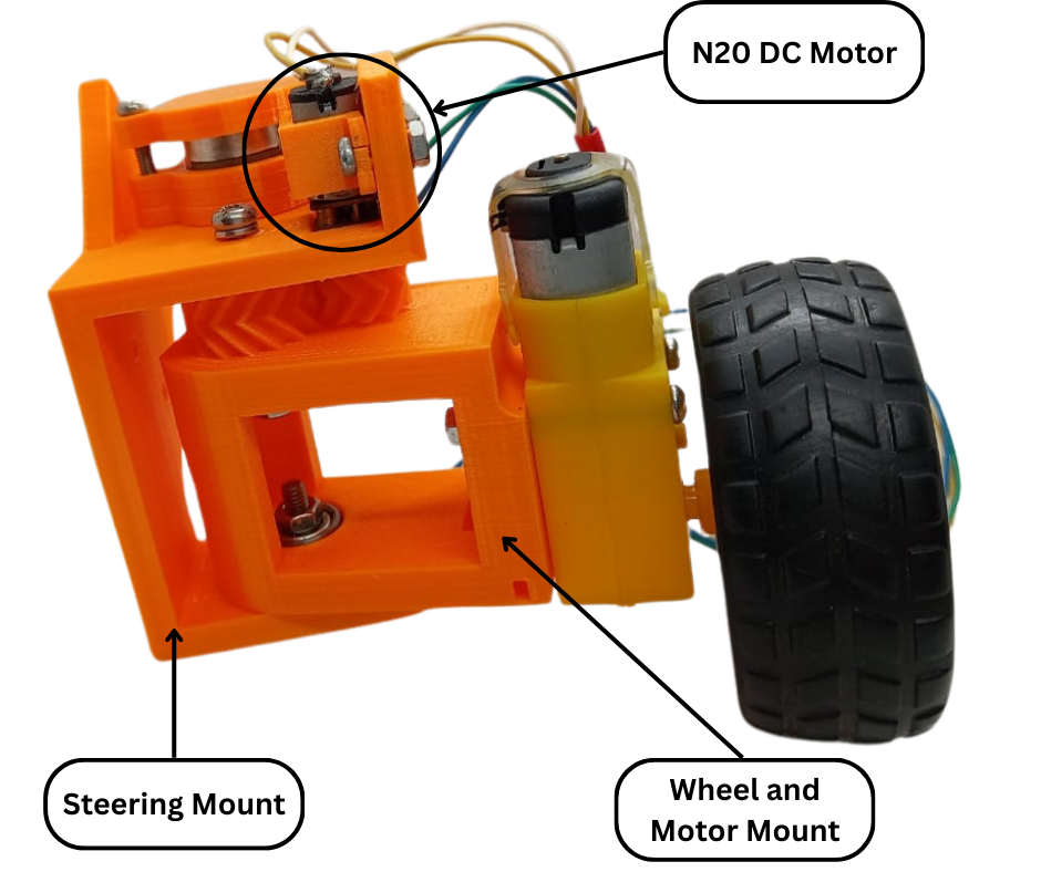
Fig.2
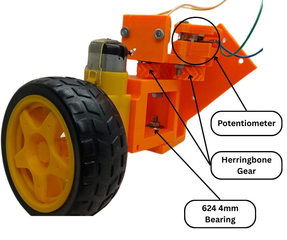
Fig.3
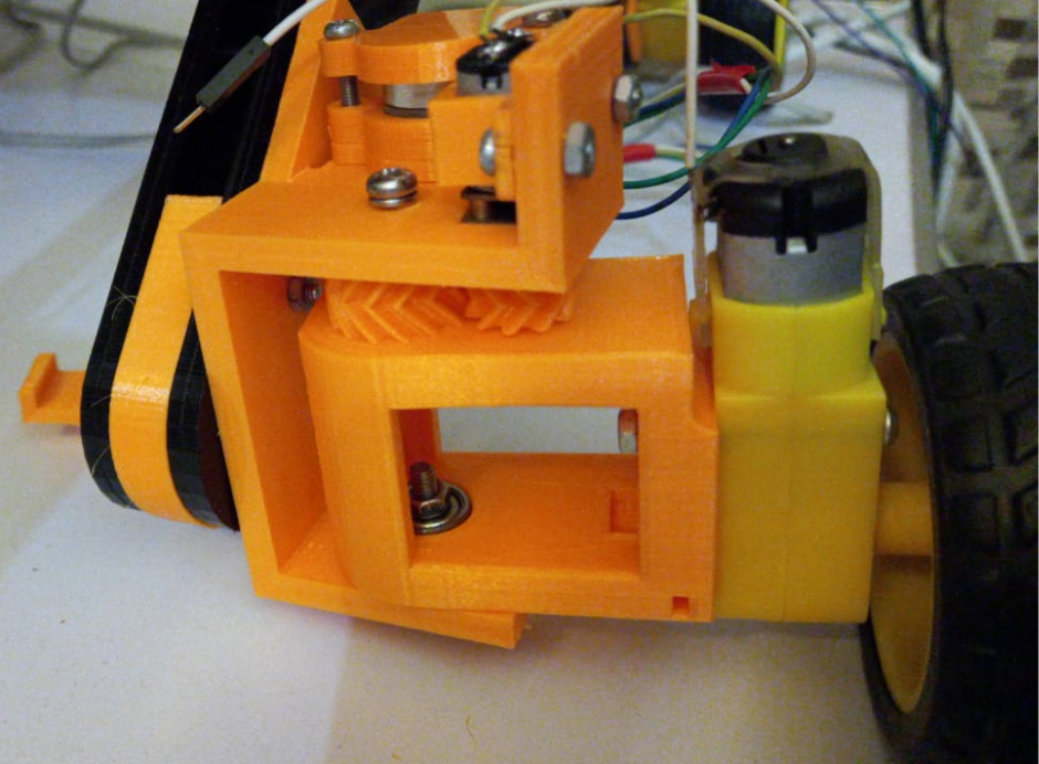
Fig.4
Fig.2 and Fig.3 show our first iteration of the steering and wheel mechanism. This mechanism consists of two 3D printed mounts, namely the steering mount and the wheel and motor mount. The steering mount connects to the rocker bogie arms as shown in Fig.4. The wheel and motor mount to which the dc motor with the wheel is attached, is mounted inside the steering mount. The wheel and motor mount is mounted inside the steering mount with 4mm bolts going through bearings and locked with lock nuts. This method of attachment allows the wheel and motor mount to rotate from side to side.
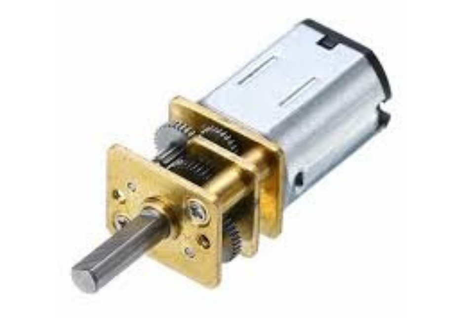
Fig.5
The wheel and motor mount has a herringbone gear on top. This gear interfaces with another herringbone gear connected to the shaft of an N20 dc motor (Fig.5) mounted to the steering mount. This dc motor when powered is able to rotate the wheel and motor mount from one side to another. This setup allows us to turn the direction of the wheel and thereby provide us with steering. In order to control how much the wheel and motor mount rotates we have added a potentiometer to this setup. The potentiometer as seen in Fig.3 is coupled directly to the n20 motor with another herringbone gear. The gearing ratio between the n20 motor, the wheel and motor mount and the potentiometer gears is 1:1:1. This means that the potentiometer shaft will rotate the same amount as the n2 gear. This allows us to know how much rotation has taken place and the angular position of the wheel and motor mount. This information is then fed into a microcontroller which then uses a PID control algorithm to control the n20 motor such that it rotates the wheel to face the direction we want and holds it there.
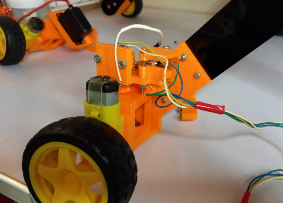
Fig.6
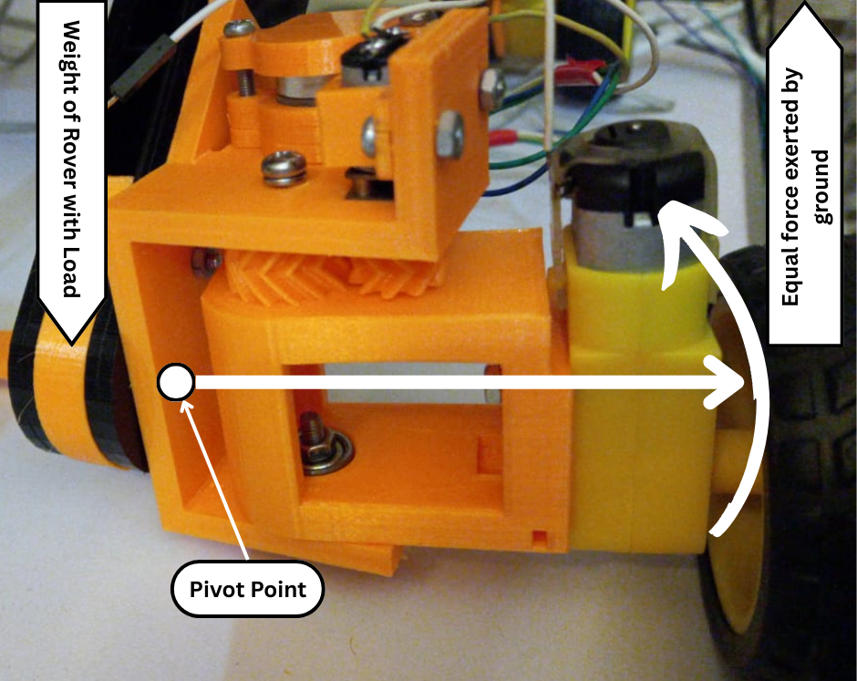
Fig.7
This setup in Fig.2 worked well in testing and when not under load. The potentiometer was able to measure the angular position of the wheel and motor mount. These readings were then used by a microcontroller such as an arduino together with the angular value that we wanted the wheel to face to accurately control the output to the n20 dc motor such that it turned the wheel and motor mount to the angular position that we programmed. But the issue with this design became highlighted when this steering assembly was attached to the rover frame as shown in Fig.6. The rover frame is sturdy and has a weight of about 2 to 3 kilos. This weight is transferred to the ground along the rocker bogie arm linkages. The steering assemblies are attached to the ends of the rocker bogie arm linkages. Therefore a downwards force is exerted on the steering assemblies as shown in Fig.7. This downward force is countered by an upward force exerted by the ground on the wheel. Since there is distance between the rover arm and the wheel, this causes a rotational moment with the pivot point being at the attachment point of the steering assembly and the rover frame arm linkage. This moment caused bending of the steering assembly as well as the rover arm linkage. The severity of bending depended on the load on the rover. To rectify this issue we changed the design of the steering assembly so that the downward force from the rover and the upwards force from the ground acted on the same point i.e the wheel.
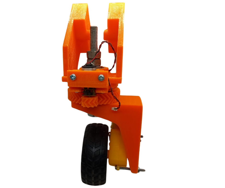
Fig.8
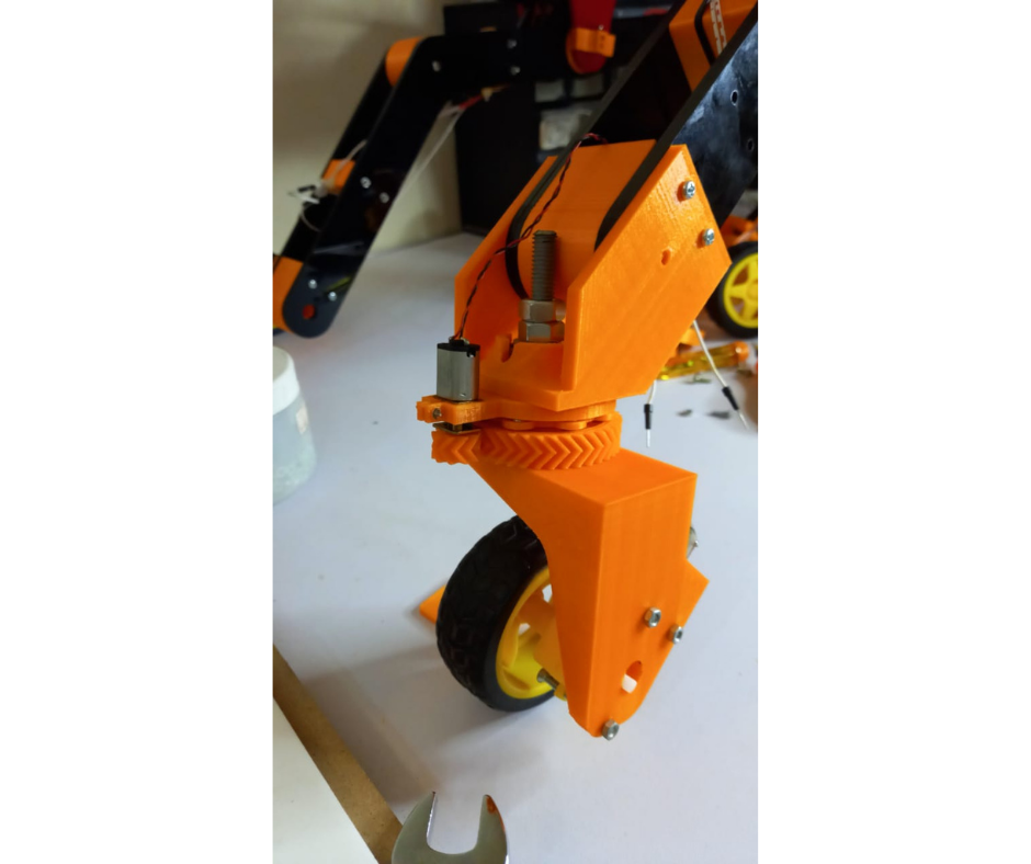
Fig.9
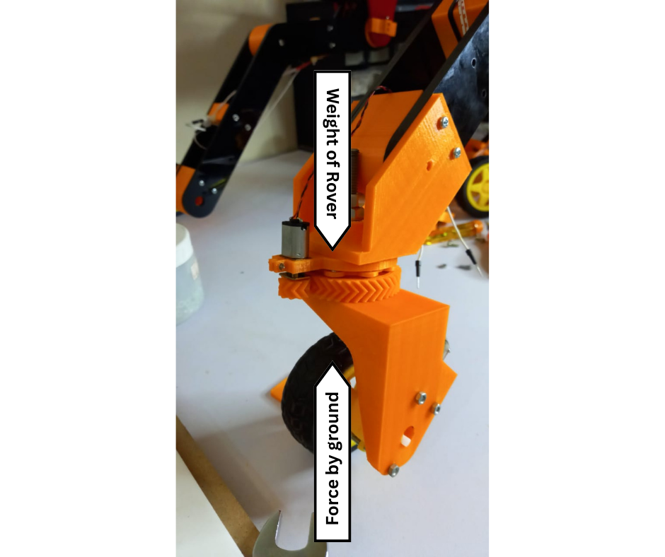
Fig.10
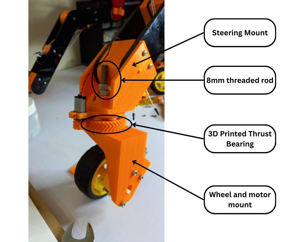
Fig.11
Fig.8 and Fig.9 shows the next iteration of the steering and wheel mechanism. As shown in Fig.10 this design prevents a rotational moment by positioning the wheel directly under the end of the point of attachment of the steering assembly to the rover arm linkage. This design also consists of two 3D printed parts, namely the steering mount and the wheel and motor mount as shown in Fig.11. The main difference between this design and the previous one apart from the positioning of the wheel is the addition of a thrust bearing.
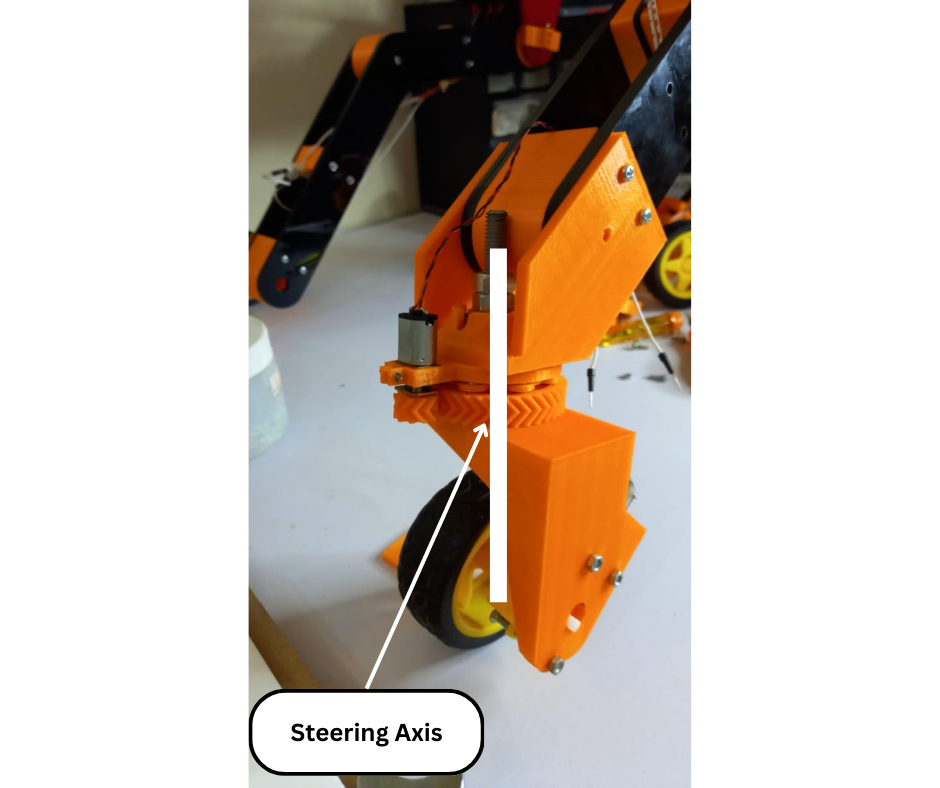
Fig.12
The purpose of this thrust bearing is two folds. The first purpose is to allow the wheel and motor mount to rotate freely about the steering axis (Fig.12). The two mounts are connected to each other by an 8mm threaded rod with the thrust bearing in between the two mounts. This allows the two parts to be connected while still allowing rotation and reducing friction. Secondly as can be seen from Fig.9 the thrust bearing has a large diameter. This large size of the bearing evenly distributes the lateral forces that the wheel and motor mount experience. This prevents too much stress on any single point on the steering mount. As can bee seen from the images the thrust bearing is also 3D printed. The design and function of this 3D printed thrust bearing will be discussed in more detail in another post in this rover project series.
As can be seen in Fig.9 we are still using the n20 dc motor to control the steering of the wheel and motor mount. This time however we are using a 3 to 1 gearing ratio between the wheel and motor mount gear and the n20 motor gear. This was done primarily to save space. We had to use a larger gear for the wheel and motor mount because of the large thrust bearing. So if we were to keep the gearing ratio 1 to 1, then the n20 motor gear would also have been large and this would have necessitated moving the n20 motor further out. We wanted to avoid that due to mechanical and aesthetic reasons.
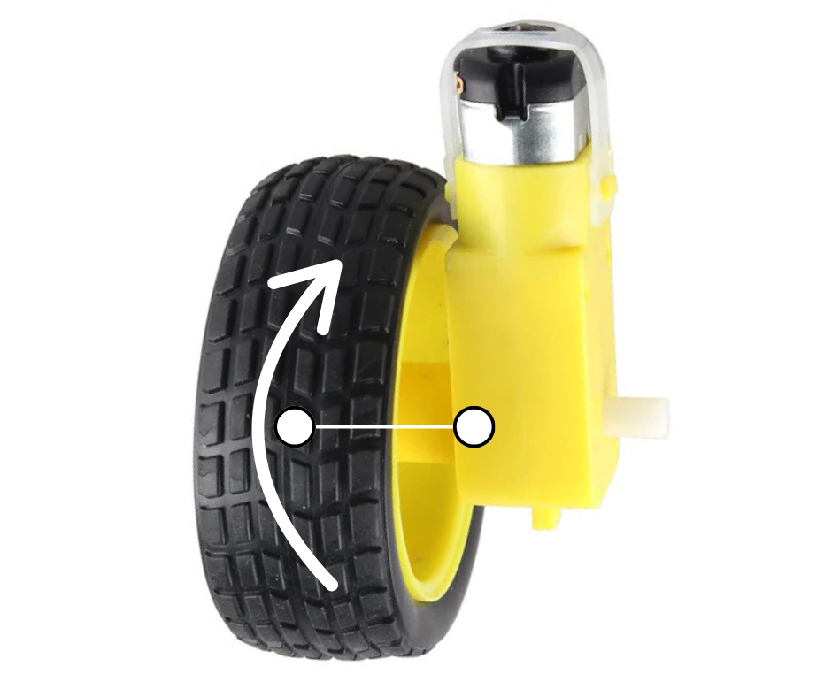
Fig.13
This iteration of the steering and wheel mechanism was also tested out. Although the n20 motor based steering and the thrust bearing performed as required, the wheel and its DC motor turned out to be the weak link of this setup. Firstly as shown in Fig.13, when the weight of the rover was applied to this wheel and motor, the wheel started experiencing a rotational moment which caused it to bend as shown. This is understandable because these motors and wheels are designed to be used in light weight RC applications and not in large robotics applications as I was trying to do. Secondly the yellow geared dc motor worked fine when the rover was on smooth level terrain. But as soon as the rover experienced an incline or a small step, these motors would stall. This again was an error on our part because we overestimated the torque capabilities of these small geared motors.
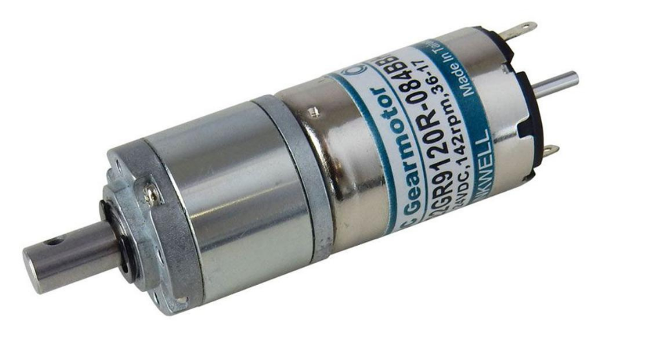
Fig.14
To solve this issue we replaced these plastic geared dc motors with high quality and much higher torque hennkwell geared dc motors shown in Fig.14. We also designed our own 3D printed wheels. We will discuss these changes to the current design in another post in this rover project series.