For better context behind the subject of this post, we suggest that you read the post titled “steering and drive mechanism part 1”. In part 1 we discussed in detail some of our earlier designs for the steering mechanism for our rover. And we discussed the issues with those designs which necessitated redesigning the steering mechanism.
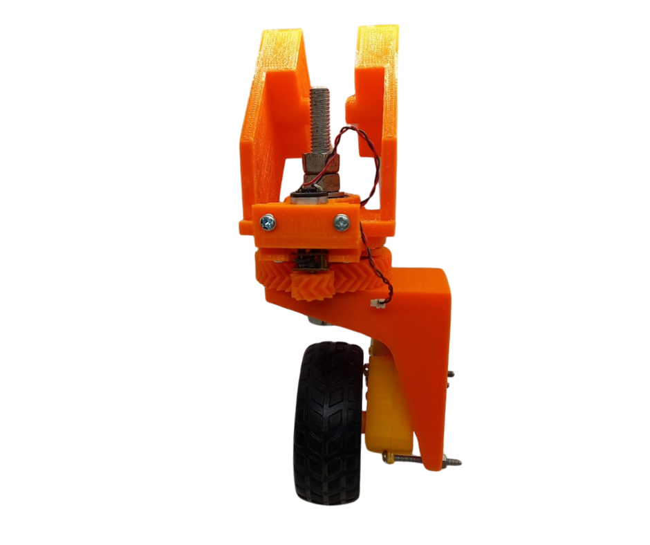
Fig.1
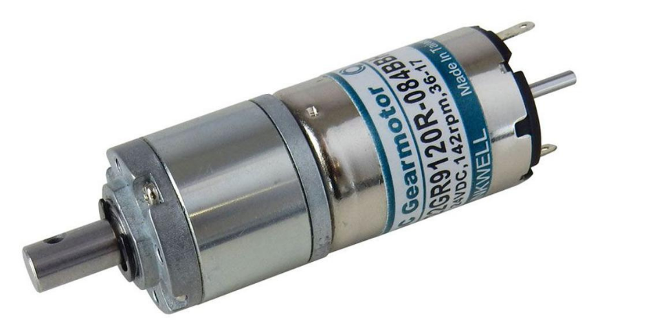
Fig.2
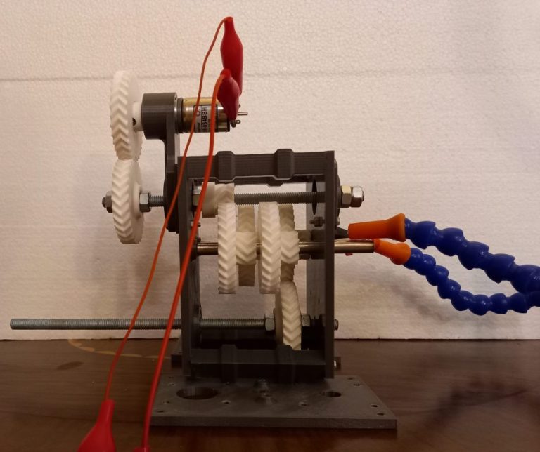
In part 1 we discussed the issues with our newest iteration of the steering design at that time (Fig.1). To solve the issue of low torque or power of the RC geared dc motors, we replaced those with high powered and high torque hennkwell geared dc motors shown in Fig.2. Another issue that we encountered after the last post was that if the rover was operated on a soft ground like sand or garden or even on gravel, sometimes the small n20 steering motors would also stall. Therefore when we were replacing the drive motors we also decided to test using the hennkwell geared motors as the steering motors as well.
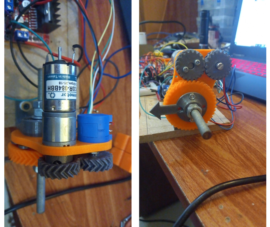
Fig.3
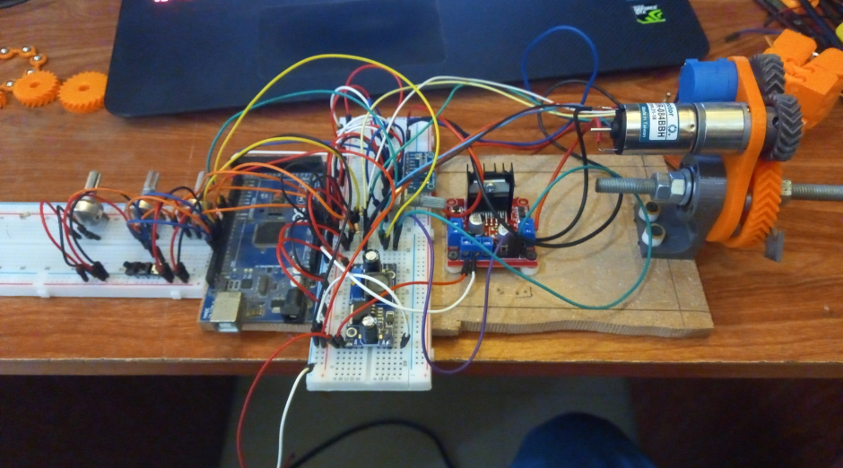
Fig.4
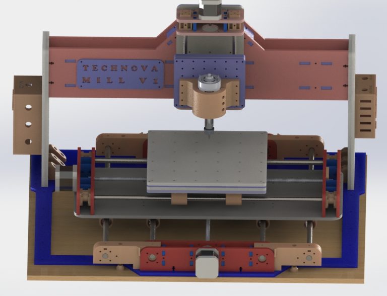
This was tested in our post titled “6WD Rover Project: 3D Printed Servo Drive with Auto Calibration” by using the test setup shown in Fig.3 and Fig.4. These tests were to determine the feasibility of developing our own servos as opposed to using commercially available ones to control steering. Following our work on making and testing our own servos, we came to the conclusion that although our custom servos worked reasonably well, the cost of all the electronics needed for each steering assembly was far more than the cost of a commercially available servo motor with high torque specifications. So we decided to put off our custom servo steering design for other robotic projects and decided to use powerful servos instead in our latest steering mechanism design.
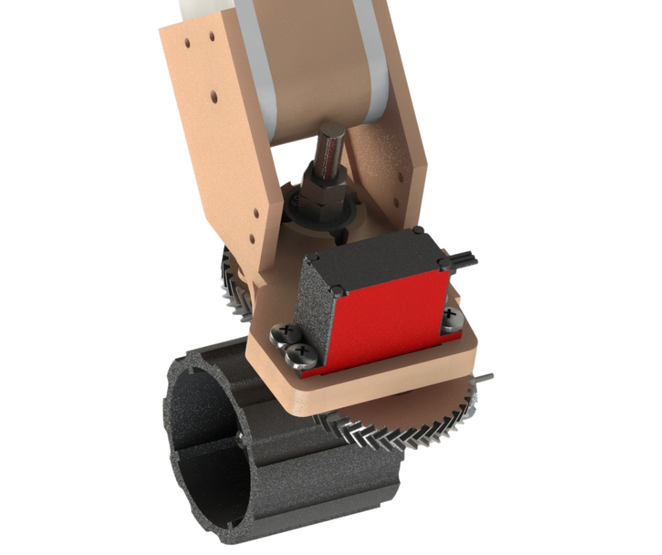
Fig.5
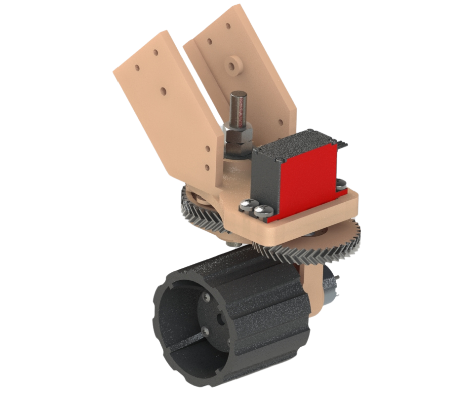
Fig.6
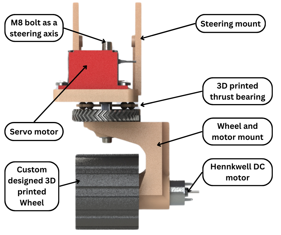
Fig.7
Fig.5, Fig.6 and Fig.7 show the latest design iteration of our steering mechanism. We kept most of the structural components of the previous design such as the steering mount and 3D printed thrust bearing. We have replaced the previously used n20 steering motor with a much powerful and much accurate servo motor. We did have to use a larger gear with the servo motor because we had to maintain a 1 to 1 gearing ratio with the wheel and motor mount gear. Using a smaller steering gear would reduce the effective steering range because the servo would turn more than the wheel and motor mount.
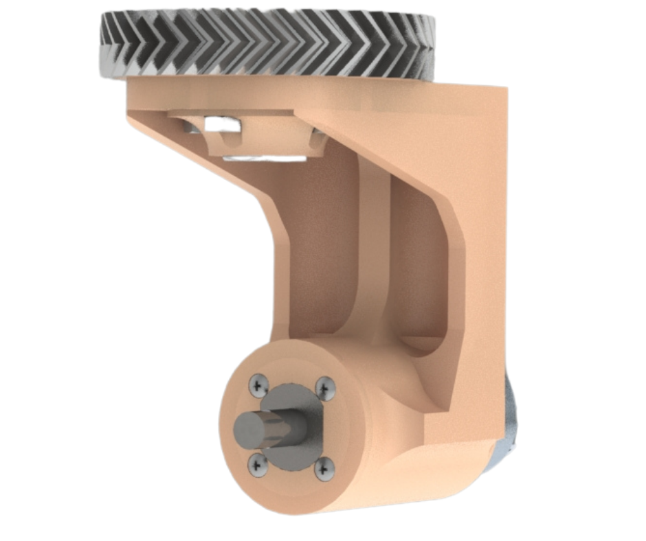
Fig.8
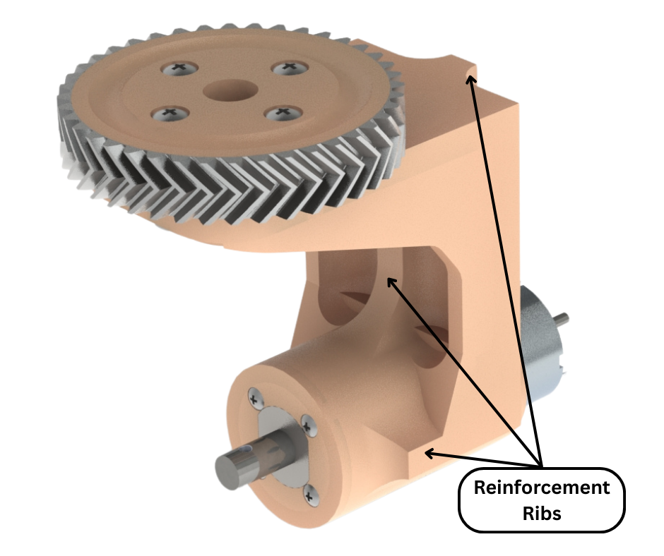
Fig.9
We modified the previous wheel and motor mount so that it is compatible with the hennkwell motor. Fig.8 and Fig.9 shows our updated wheel and motor mount. The motor is inserted into the mount and then bolted into place. A herringbone gear is bolted to the top of the mount and is used to turn the wheel and motor mount about its steering axis. This gear also forms the bottom half of our custom designed thrust bearing. We have also added significant reinforcements to the design of this wheel and motor mount to better handle the load that is applied to it when it is installed on the rover.
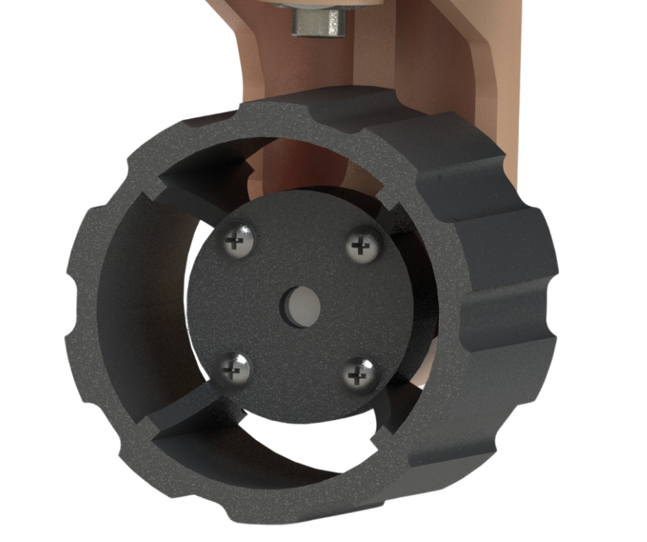
Fig.10
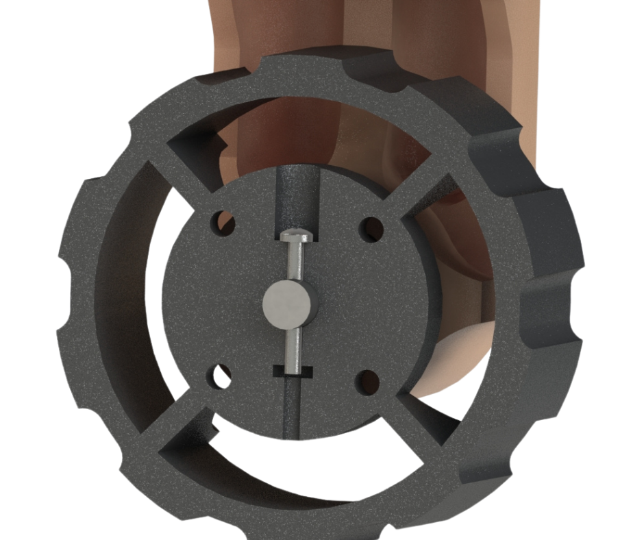
Fig.11
We also designed custom wheels for the rover. We designed our own wheels because it gave us freedom in parameters such as wheel diameter, thickness, mounting options and shape. Our wheel design can be seen in Fig.10 and Fig.11. To give our wheel better grip we did not simply make it round, but gave its surface crests and troughs. These are especially useful on softer ground. After production we also applied anti-slip foam to the crests of each wheel to add more grip when driving on a smooth surface. Our wheel is a two part component as shown in Fig.11. The first half goes over the drive motor shaft. A pin is inserted to lock the wheel with the motor shaft and prevents the wheel from coming off. The second wheel half is then bolted to the first half and thereby forms the complete wheel.
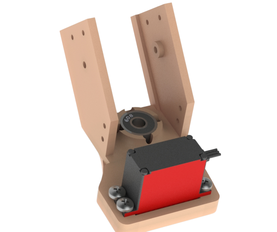
Fig.12
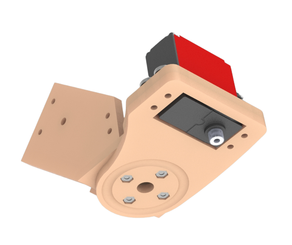
Fig.13
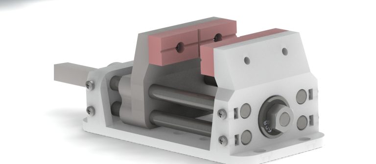
Fig.12 and Fig.13 show our steering mount. This attaches to the ends of the rocker bogie arm linkages of the rover. The servo motor that controls steering is attached to this mount. A 608 bearing is also installed in this mount. An M8 threaded rod goes through this bearing to attach to the wheel and motor mount as shown in Fig.7. M8 nuts then clamp down on this bearing. This holds the steering and motor and wheel mounts together. The steering mount also forms the top half of our custom designed thrust bearing as shown in Fig.13. The herringbone steering gear shown in Fig.6 attaches to the shaft of the servo motor. This steering gear is coupled with the gear on the wheel and motor mount. Together this allows the servo motor to turn the wheel and motor mount, thereby turning the direction of the rover wheel.
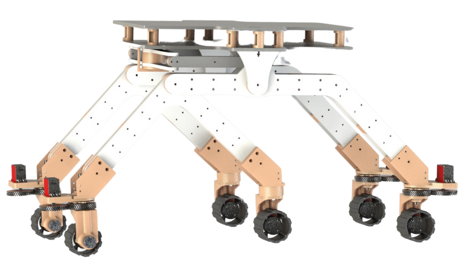
Fig.14
Fig.7 shows all the mounts and gears assembled together. Fig.14 shows the entire rover completely assembled. As can be seen the middle bogie arm linkages do not have steering because it was not needed. These center wheels are directly under the center of the rover and act only as the followers. The center drive unit design is shown more clearly in Fig.15 and Fig.16.
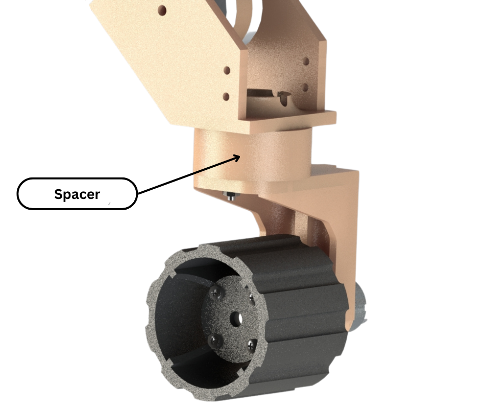
Fig.15
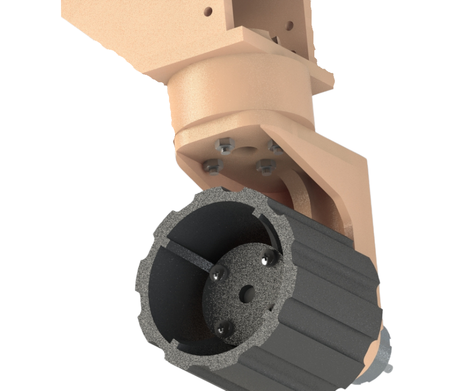
Fig.16
Since these wheels are only followers and do not need steering, the servo and thrust bearing assemblies are replaced with a 3D printed spacer block that rigidly connects the steering mount to the wheel and motor mount using bolts.
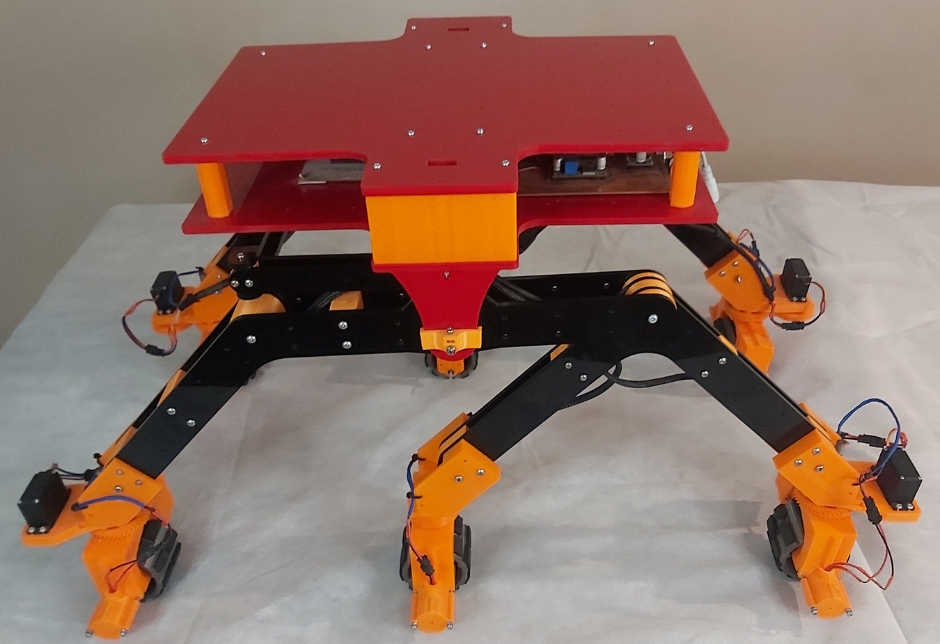
Fig.17
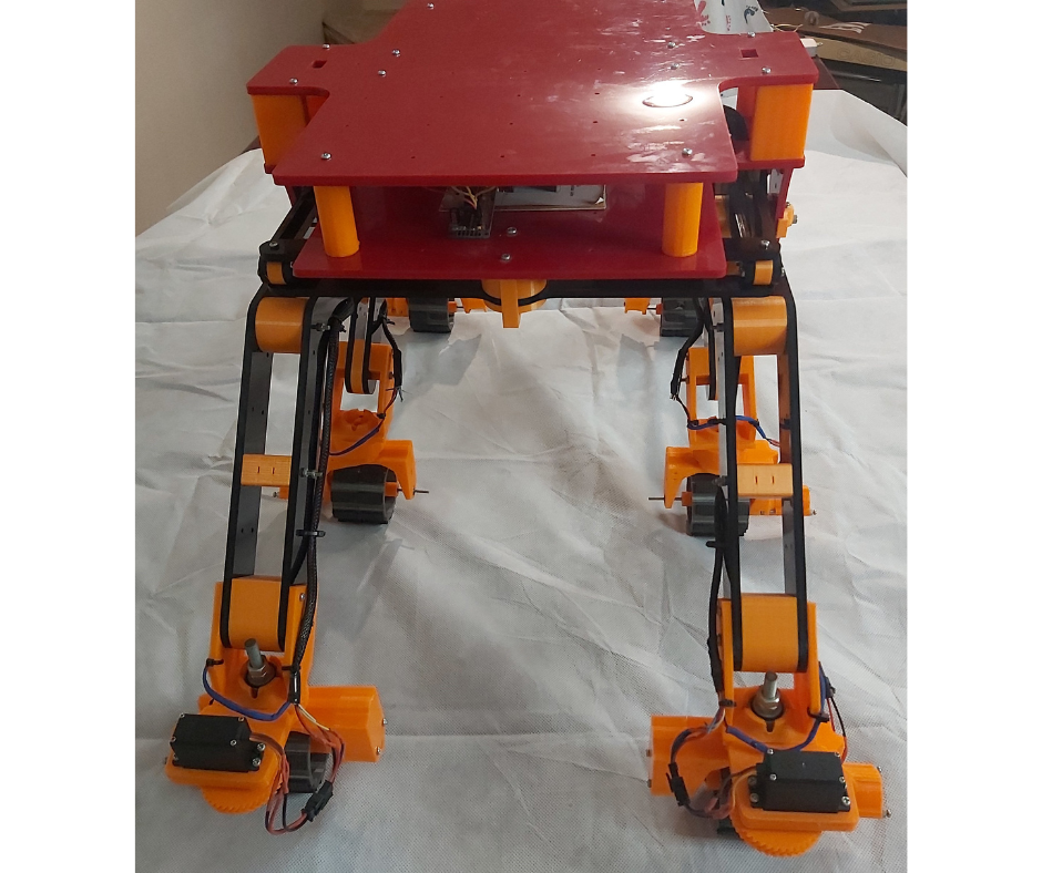
Fig.18
Fig.17 and Fig.18 shows our rover manufactured and ready for testing. In our next post we will briefly discuss the electronics side of the rover and also test the rover’s drive and steering. We will also test the rover’s capabilities when traversing uneven terrains and obstacles.