We have been working on a couple of gripper ideas for our Robotic arm and Rover projects. In our last post we explored the pincer type two finger gripper design that is quite commonly found on hobby robotic arms because it is easy to design, make and assemble. In this post we will explore a four finger gripper design.
Fig.1 through Fig.6 explores and labels the different components of our design. All components shown in this design apart from the fasteners and motor are designed to be 3d printed. We have opted to use our favourite hennkwell geared dc motor again for this project. The motor shaft is coupled to a segment of M8 threaded rod using a coupler. This threaded rod interfaces with M8 nuts embedded in the actuator plate. This way when the motor shaft turns, the threaded rod also turns and thereby moves the M8 nuts with the actuator plate up or down . The actuator plate in turn pulls or pushes the arm linkage causing the gripper jaws to either open or close. This mechanism is better explained visually in the demonstration video.
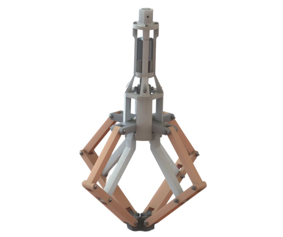
Fig.1
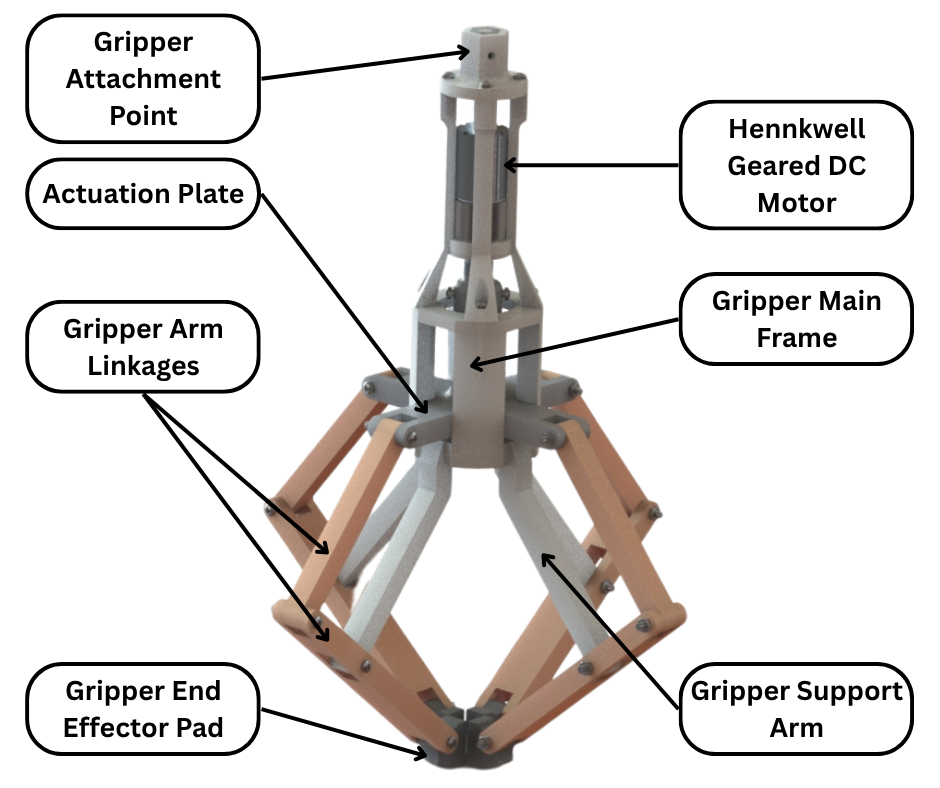
Fig.2
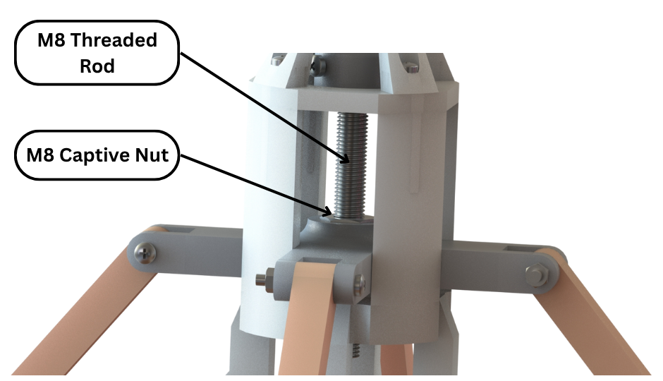
Fig.3
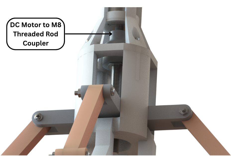
Fig.4
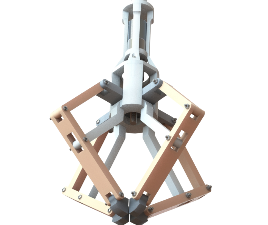
Fig.5
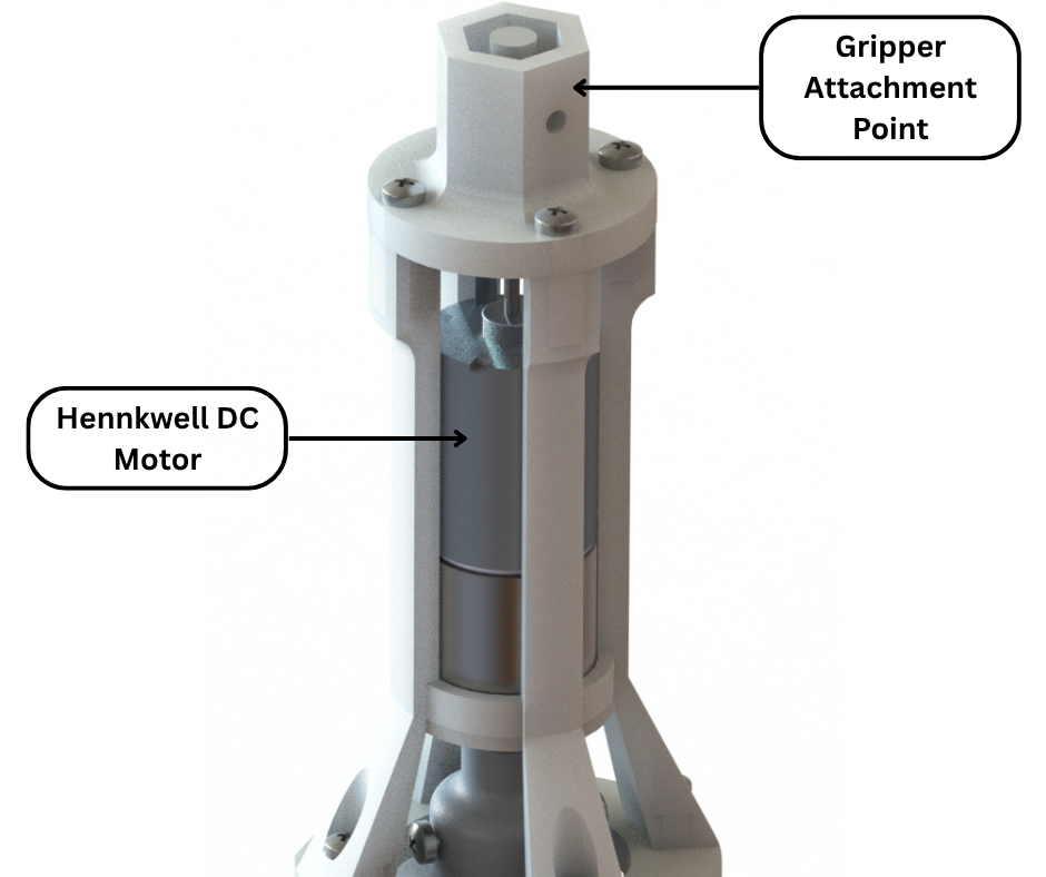
Fig.6