In this post we will be outlining a major update to our Acriprint V2 3D printer. We completely redesigned the X axis of our 3D printer. First we will briefly discuss the need for such a major change in the design.
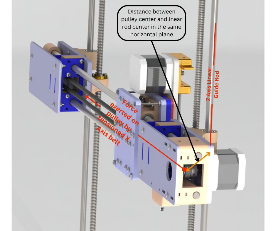
Fig.1 shows the original design of the X axis of our 3D printer. This has been discussed in detail in an earlier post. The X axis of our printer consists of 3 main assemblies of parts. There is the X axis motor mount assembly, the idler mount assembly and the extruder and hotend assembly. All three assemblies are made using both 3d printed and laser cut acrylic parts that are connected together using fasteners. The reason for using two types of parts was that since the frame of the printer was already being made using laser cut acrylic panels, it was faster and cheaper to manufacture the larger parts of these three assemblies out of laser cut acrylic as well. Issues with this method were realised after assembly and use over many hours. The weight of these assemblies were increased when we added the weight of all the fasteners required to connect all the different parts of these assemblies. There was an issue of correct alignment of parts that needed accurate placement with respect to each other. Locknuts had to be used in some critical areas to ensure that they did not come loose due to the presence of unavoidable vibrations when the printer was in use. Fig.1 also highlights an issue with the design of the X axis itself. As can be seen in the figure, there is a distance in the horizontal plane between the center of the X axis drive pulley and the center of the LM8uu bearing that is mounted on the Z axis linear guide rods. Same is the case for the idler assembly. When the X axis timing belt is tensioned using the tensioning mechanism in the idler assembly, a horizontal force is applied on the drive pulley that pulls it towards the center of the whole X axis assembly. Vice versa for the idler pulley on the idler assembly. Since the center of the pulley and the linear bearing are not in the same X axis plane, this causes a turning moment of the motor mount assembly about the Z axis guide rod. This problem in addition to causing issues in alignment between the X axis motor mount and idler assemblies, also added a force/stress on the Z axis leadscrews perpendicular to the turning axis. This not only causes excess wear of the leadscrews but also exaggerates the issue of Z banding which leads to wave-like artifacts in the 3d prints.
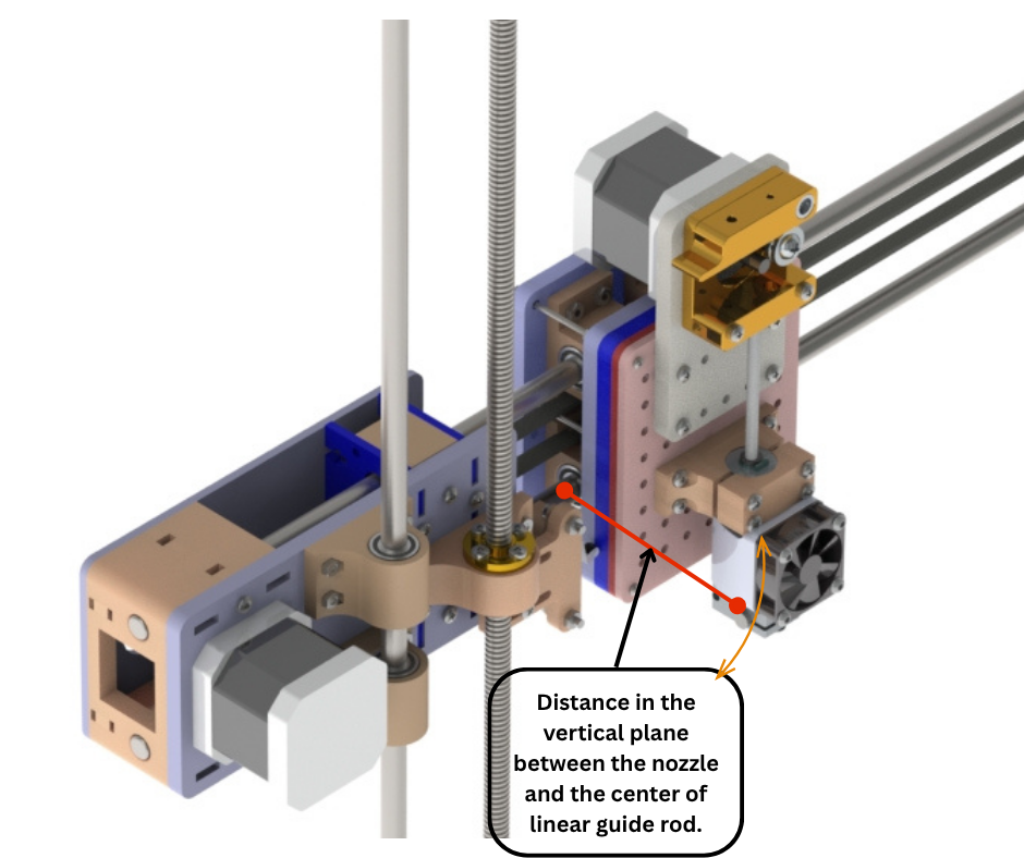
Fig.2 shows another issue with the design of the X axis. There is again a distance between the centers of the linear bearings of the extruder and hotend mount assembly and the center of the hotend nozzle. Since we do not machine the linear rods ourselves, they are usually undersized by an average of 0.1 millimeters. This difference along with the tolerances of the lm8uu linear bearings mean that there is room for minor radial movements when the bearings are installed on these linear rods. So the weight of the hotend along with the cooling fans cause a turning moment of the whole assembly about the linear bearings. This is shown in Fig.2. This off center weight distribution gives rise to unwanted artifacts or imperfections in the 3d prints. During operation when the heavy Y axis printbed is accelerated or decelerated rapidly, vibrations are induced in the printer that also induces minor vertical movements in the hotend assembly due to the offcenter weight distribution discussed above.
To address these issues we have had to rethink and redesign the entire X axis gantry. Now we will discuss the newer design of the three main assemblies of the X axis.
Fig.3 to Fig.9 shows the new completely 3D printed X axis motor mount assembly. Making this and the other assemblies completely 3D printed allowed us to be able to rapidly change and improve the design without having to wait for laser cut acrylic parts to be made. 3D printing reduces the complexities and weight by reducing the number of parts and fasteners needed. It also allows flexibility in design by allowing addition of features that are not possible with laser cut parts. A major change that we have done in this version is to essentially rotate the entire X axis by 90 degrees. The X axis linear rods are now in a horizontal plane (Fig.28) rather than a vertical plane that they were in previously (Fig.2). Secondly we have aligned the stepper motor axis, linear bearing axis and Z axis leadscrew nut axis such that they all now are in the same vertical plane. This solves one of the main issues with the previous design as discussed at the start of this post. Since the motor, linear bearing and leadscrew axes are in the same plane, the force by the X axis timing belt (when the timing belt is tightened) acts perpendicularly to all three of these axes. This eliminates the moment of the motor mount about the Z axis linear rod because now all the three axes and the force by the belt are in a single plane. The LM8UU linear bearings that allow the X Axis gantry to move along the Z axis linear rods are pressfit into the motor mount as shown in Fig.6 and Fig.7. They are then secured using zip ties. These bearings are then further secured using 3D printed covers as shown in Fig.3. We have preserved the concept of adjustable X axis limit switch as shown in Fig.3 and Fig.9. The limit switch can be extended or retracted by loosening and then retightening the bolts shown in Fig.9. The X axis linear rods are installed in the motor mount from the back as shown in Fig.4. Once the rods are installed, the linear rod locking rod locking bolts are tightened to lock the X axis linear rods in place.
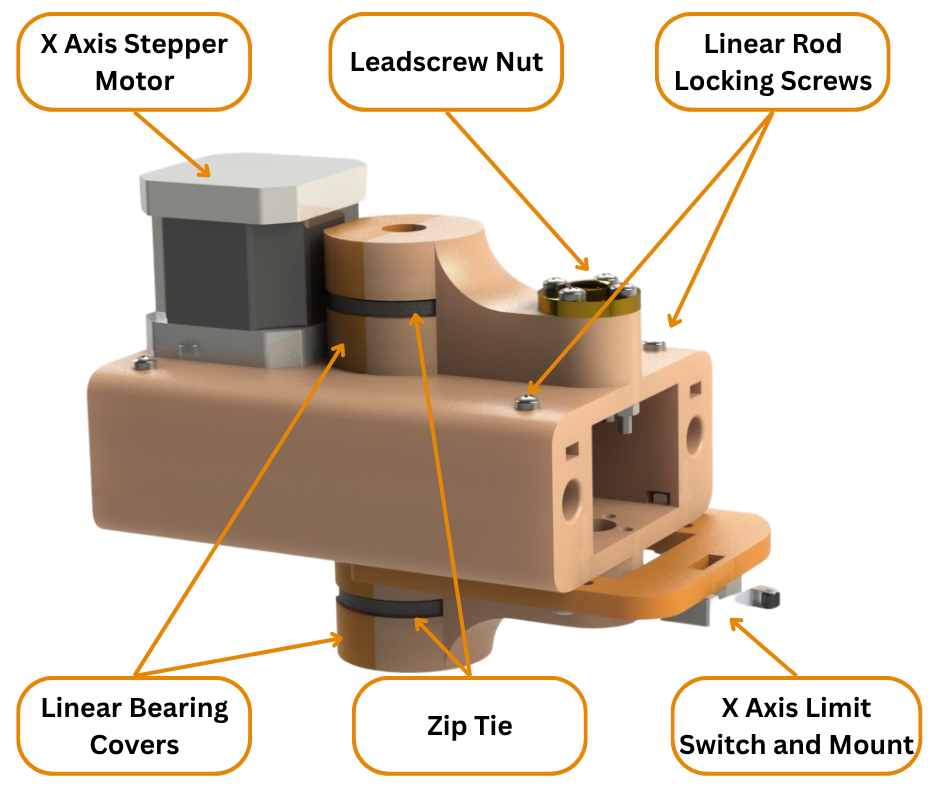
Fig.3
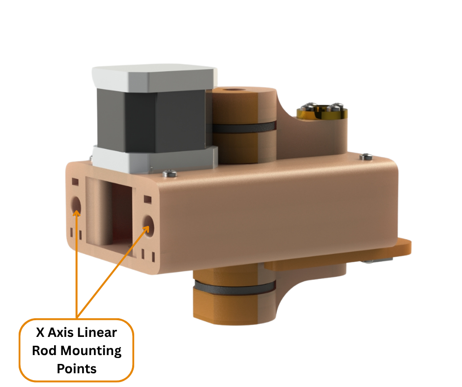
Fig.4
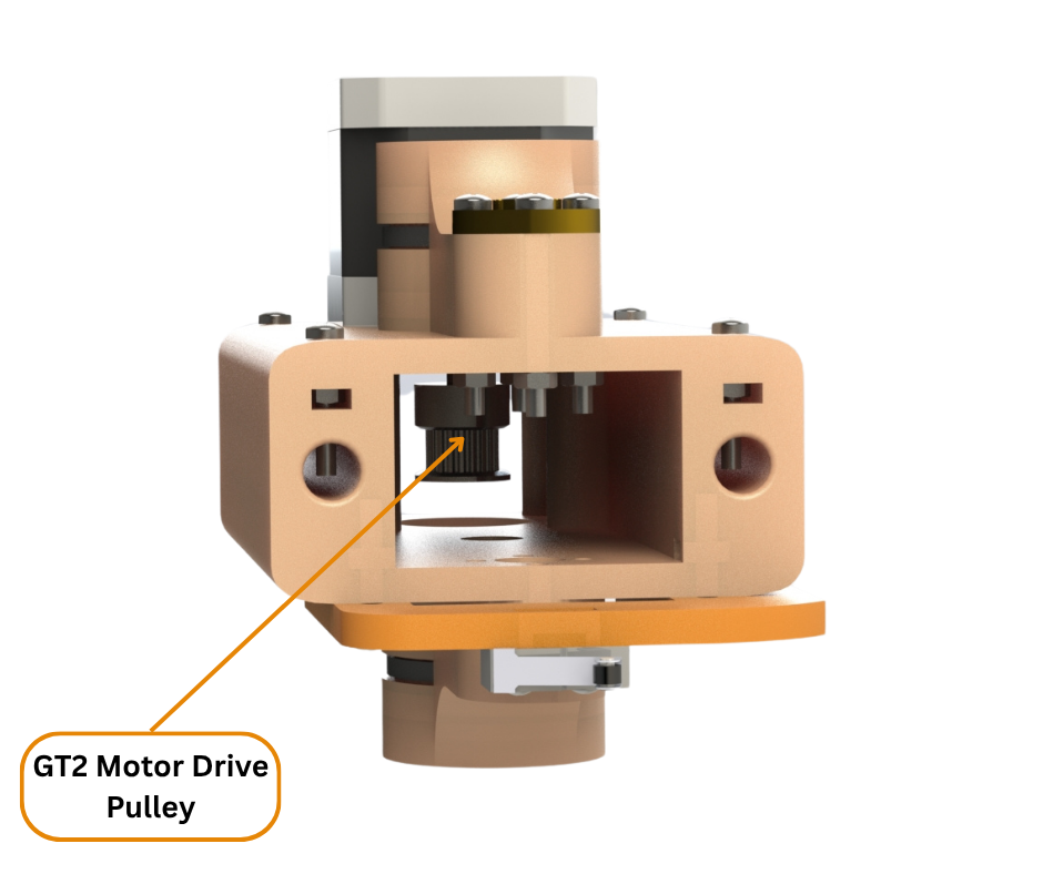
Fig.5
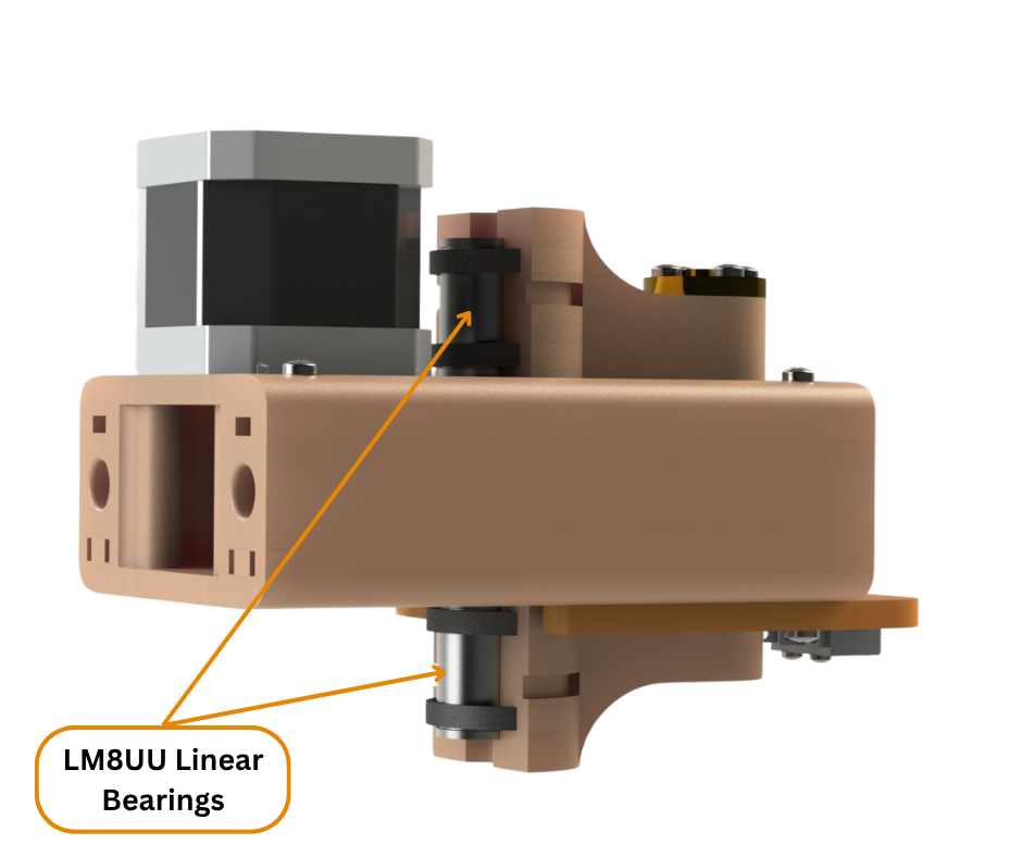
Fig.6
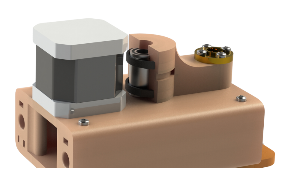
Fig.7
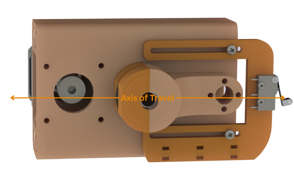
Fig.8
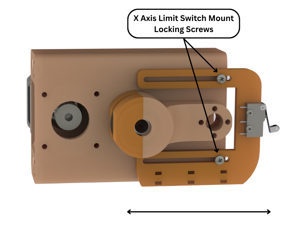
Fig.9
Fig.10 to Fig.15 shows the new and also completely 3D printed X axis Idler mount assembly. The general features like the overall design, linear bearing mounts, etc are the same as in the X axis motor mount assembly. The X axis belt tensioning system is similar to the one used in the previous design except that it is now rotated by 90 degrees. The figures are self explanatory.
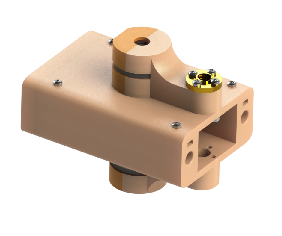
Fig.10
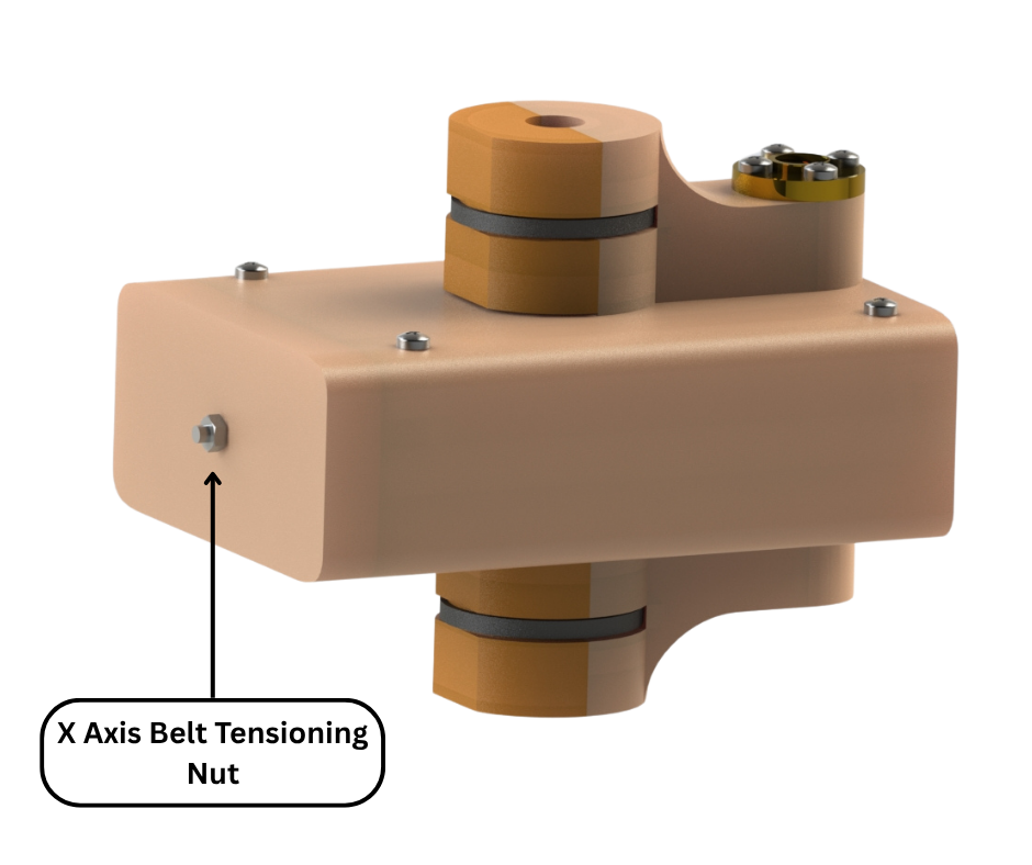
Fig.11
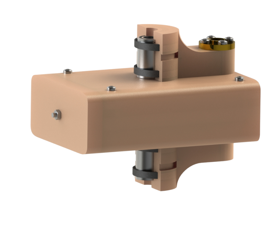
Fig.12
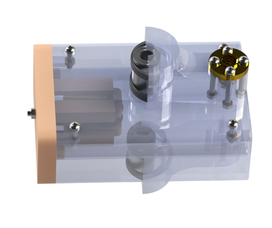
Fig.13
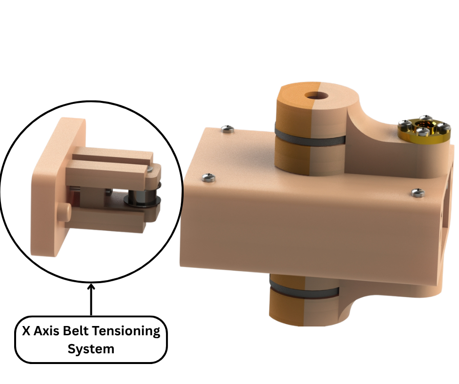
Fig.14
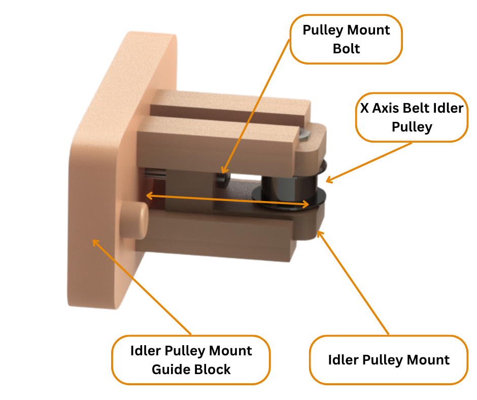
Fig.15
Fig.16 to Fig.27 shows the new X axis extruder mount assembly. The design of this assembly has taken the most amount of time designing, testing and redesigning because of its critical functions. We wanted to retain the useful features of the previous design such as the modular mount design and the quick connect board for easy changing and upgrading of motors and/or hot-end assemblies.
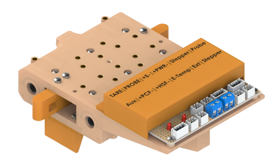
Fig.16
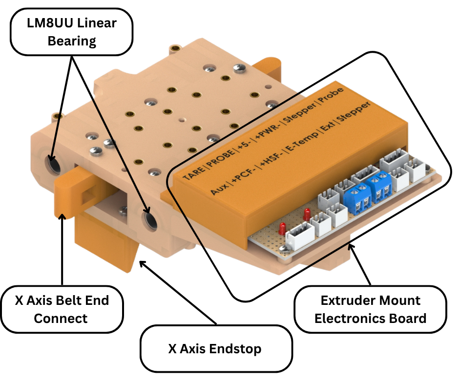
Fig.17
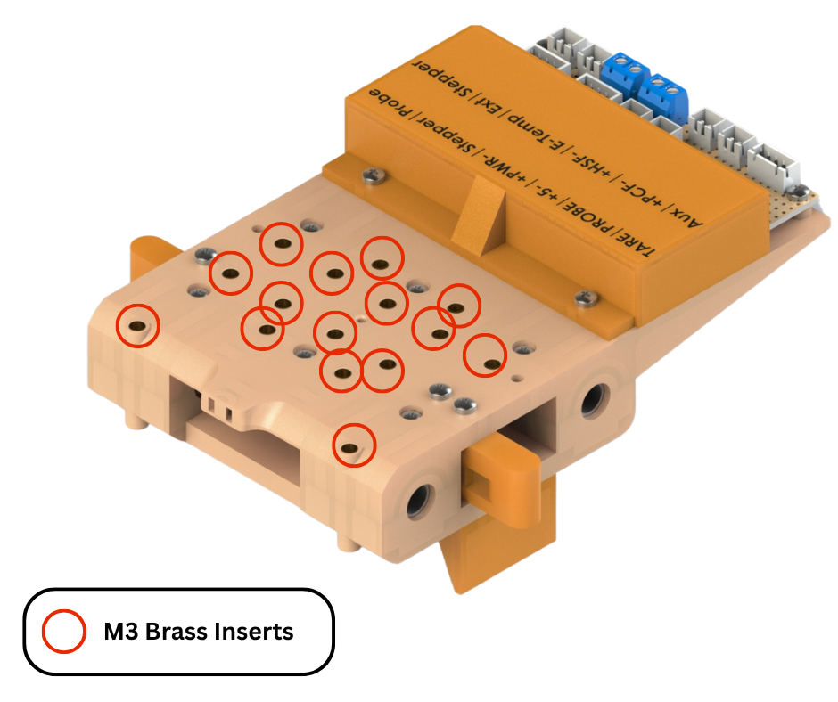
Fig.18
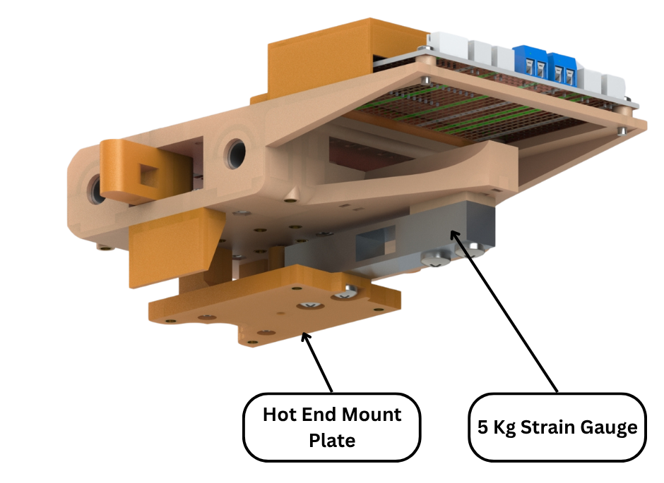
Fig.19
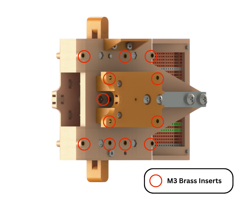
Fig.20
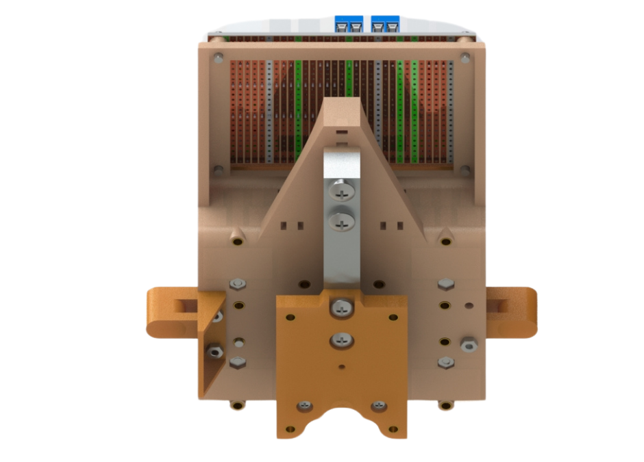
Fig.21
One of the major changes in the design as compared to the previous design is that we have essentially rotated the whole assembly by 90 degrees. The hot-end assembly is now directly below the center of the extruder mount assembly as shown in Fig.24. This solves the issue of off-center weight distribution in the old extruder mount assembly discussed above. The solution of this issue is highlighted in Fig.26. Now all the vertical forces act on the center of the extruder mount assembly. These forces are then evenly transferred to the X axis linear rods via the linear bearings. Since the forces are evenly distributed across the two linear rods, the issue of moment about the rods is solved. This solution improves the rigidity of the extruder assembly which then directly translates into better prints and less artifacts.
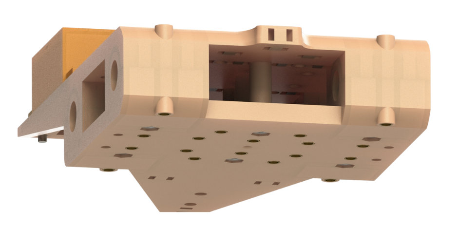
Fig.22
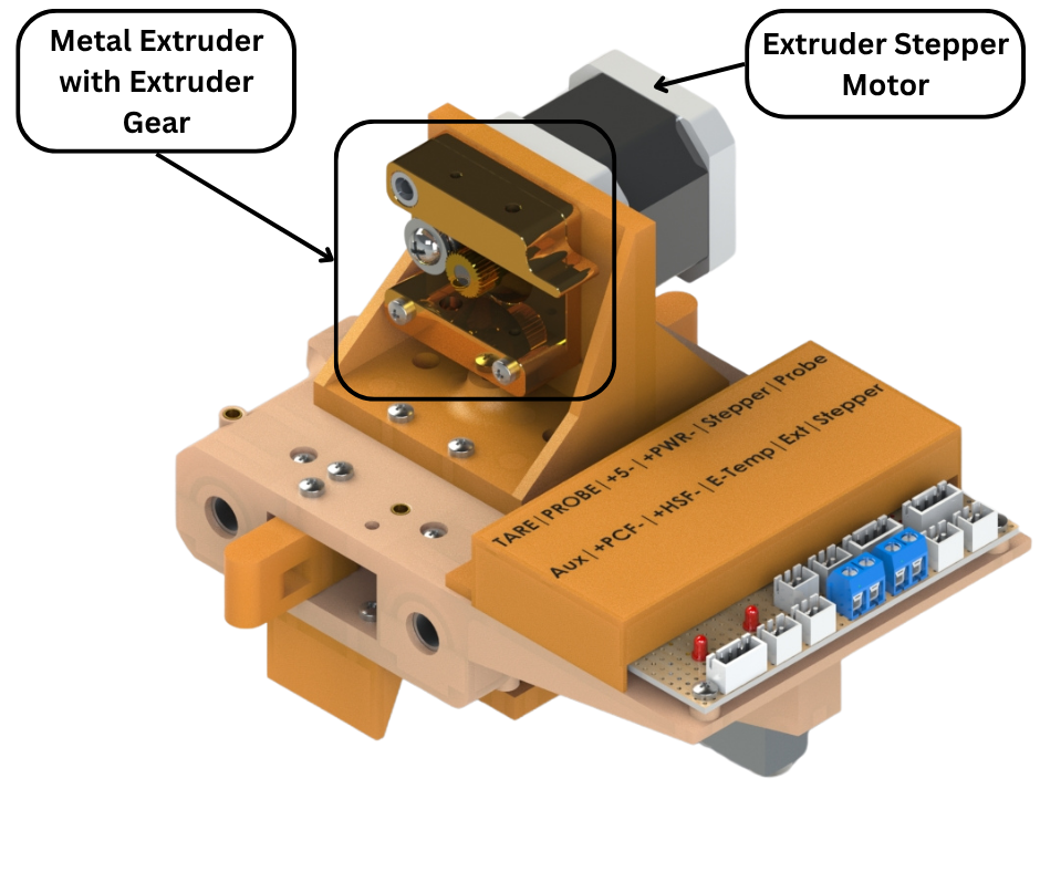
Fig.23
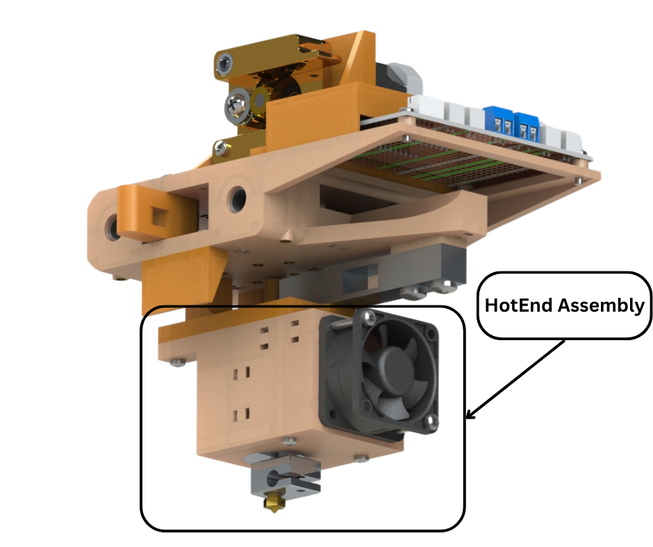
Fig.24
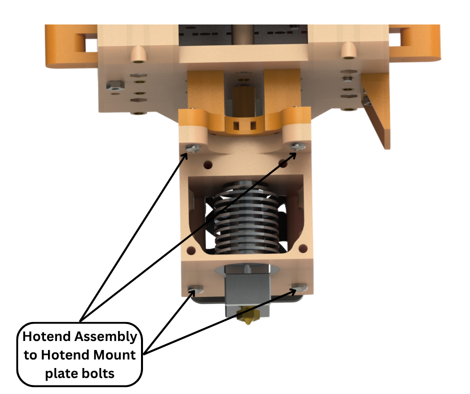
Fig.25
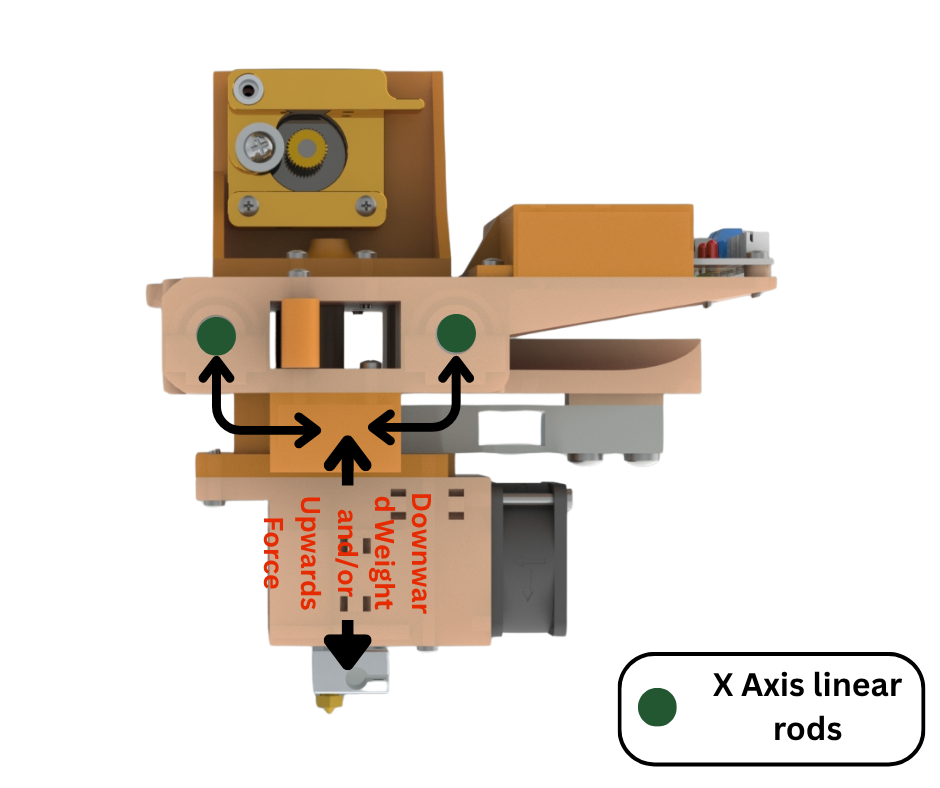
Fig.26
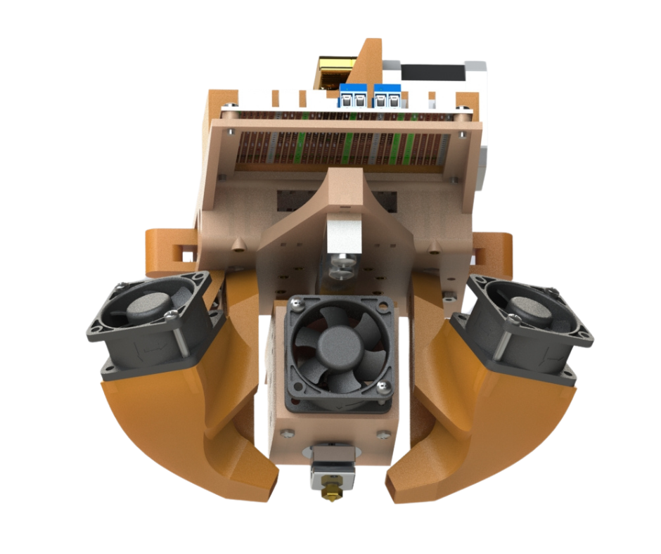
Fig.27
Fig.16 to Fig.21 shows the main extruder mount assembly. This structure provides the basis for attaching different modules to it such as the extruder motor assembly and the hot-end assembly. This ease of attachment and detachment of modules is made possible by the many M3 threaded inserts installed in the structure as shown in Fig.18. These inserts allow components to be easily attached and detached. These inserts are arranged in a specific pattern with uniform spacings to make designing of attachable modules easier. This pattern is on both the top and bottom surface of the main extruder mount assembly.
Fig.19 shows the underside of the main extruder mount assembly. We have a strain gauge that is attached to the hot-end assembly mount plate. The stain gauge is connected to the electronics on the extruder mount electronics board. When a vertical force is applied to the hot-end assembly mount plate, the strain gauge registers a reading. These readings allow us to quantify the amount of force being applied to the hot-end assembly mount plate. This allows us to implement very useful features such as automatic bed levelling and automatic Z axis alignment on our 3d printer. Both of these features will be discussed in a future post.
Fig.24 and Fig.25 shows how a hot-end assembly is attached to the hot-end assembly mount plate. The hot-end assembly mount plate also has four M3 threaded inserts installed in it that allow attachment of the hot-end assembly using four M3 bolts.
Having the ability to quickly attach, detach components to upgrade or repair can not be understated. A very small example can be seen in Fig.27 where we can very easily attach two large parts cooling fans when needed without having to change other components.
Fig.28 to Fig.32 show the entire assembled X axis gantry that moves vertically along the Z axis linear rods.
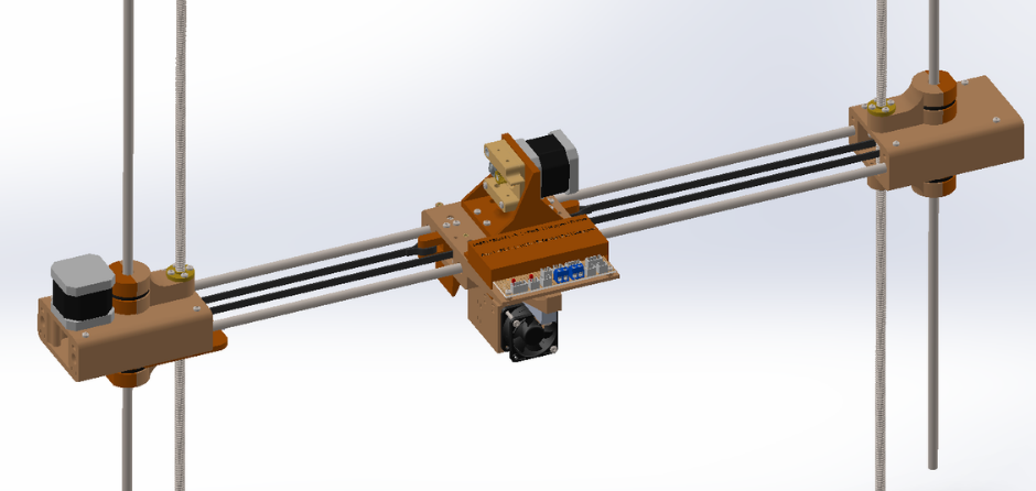
Fig.28
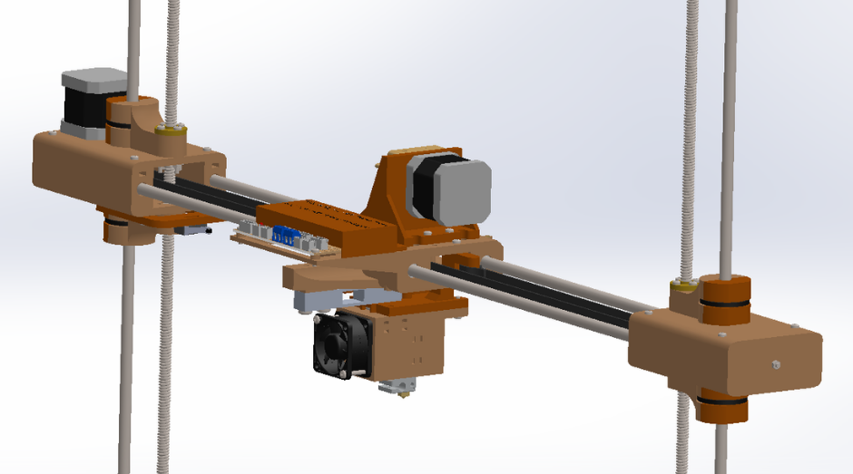
Fig.29
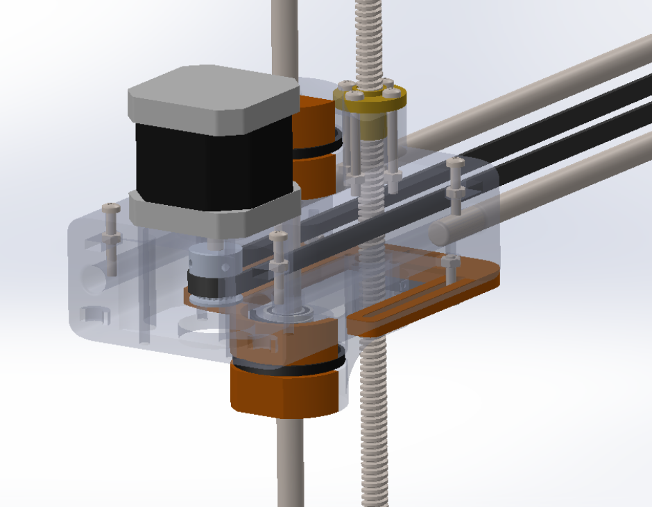
Fig.30
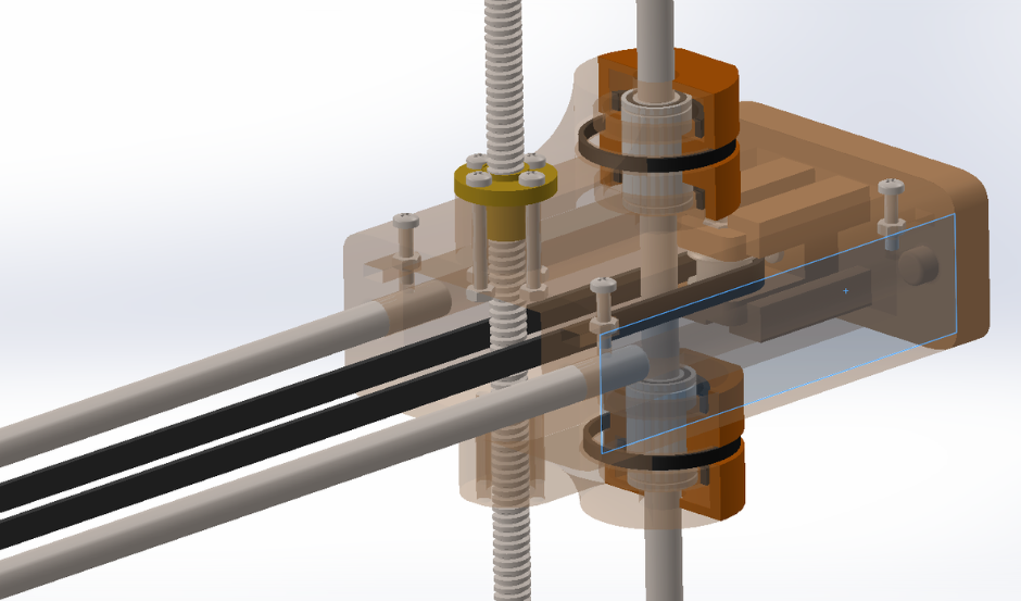
Fig.31
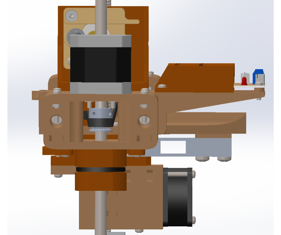
Fig.32