After completing the design, fabrication and assembly of our Acriprint V1 3D printer, we tested it for about a year. We 3D printed a lot of parts with it including parts for other machines as well. We also 3D printed a significant amount of open source models available on websites such as “Thingiverse”. The printed results are posted at the end of the project post titled “Acriprint Version 1”. These were primarily to test the performance of our 3D printer and put it through its paces.
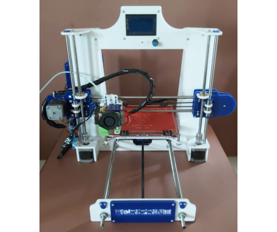
Fig.1
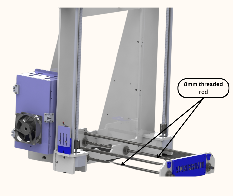
Fig.2
These testing uncovered a lot of areas of the 3d printer that could be improved. The biggest issue was the lack of rigidity of the printer. Since the frame of the printer was made from only 6mm thick acrylic panels joined together, the frame was light but not rigid. The printer front panel was connected to the main printer frame using M8 threaded rods and nuts only as shown in Fig.1 and Fig.2. Since the threaded rod segments were long, this part of the printer construction was prone to bending and shifting which caused bed levelling issues. We needed a 3d printer frame design that had all the pieces rigidly connected to each other. At this time since we were more familiar with using laser cut acrylic, we decided to design the frame for our newer version of 3d printer from acrylic. This time however we were going to make it much more sturdier and rigid.
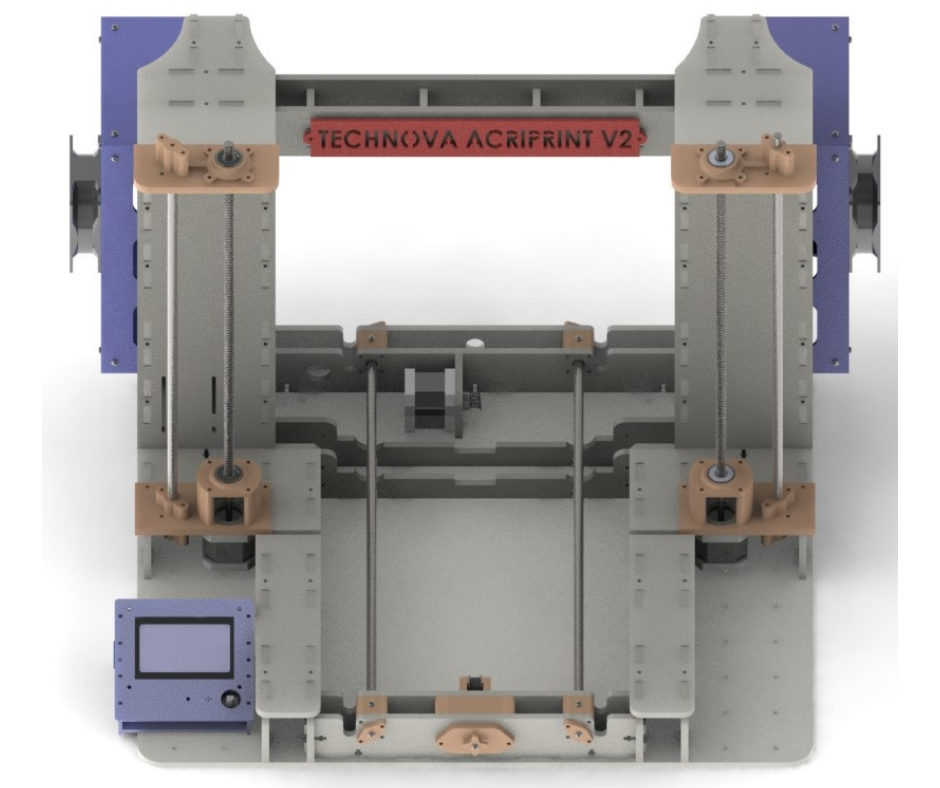
Fig.3
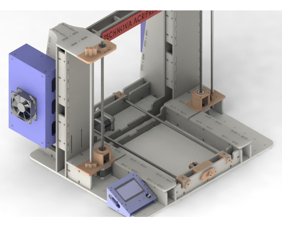
Fig.4
Fig.3 and Fig.4 shows the semi assembled frame design of our latest version of our 3d printer. We will now discuss the features of our frame design and the thinking behind those features. Like version 1 of our 3d printer, this latest frame design also has the same structures that join together to form the overall frame of the printer. Fig.5 and Fig.6 highlight these structures which we will now discuss individually.
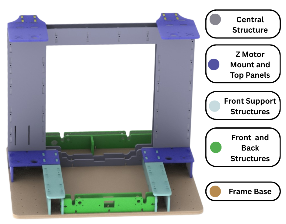
Fig.5
Fig.6
Central structure
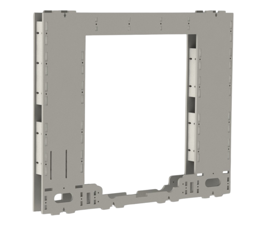
Fig.7
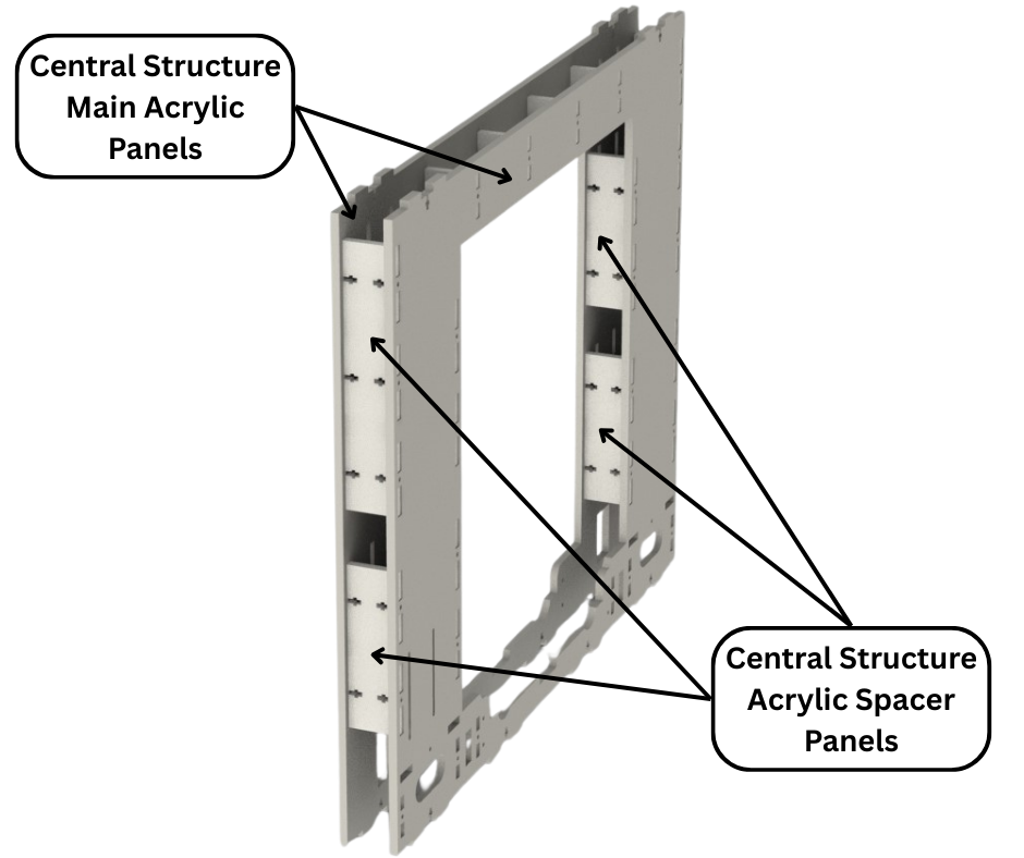
Fig.8
Fig.7 and Fig.8 show the central and largest structure of the frame other than the base. This main structure provides a connection point for all the other structures that form the entire frame. This structure is also made from 6mm thick acrylic panels connected together. The major difference is how we have connected the panels this time to ensure structural stability and rigidity. To increase the thickness of this structure and the others without increasing the thickness of the acrylic panels, we use two panels joined together with spacer panels to form an overall thicker and more rigid structure as shown in Fig.8.
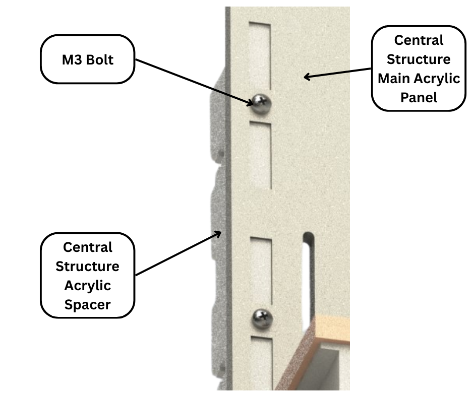
Fig.9
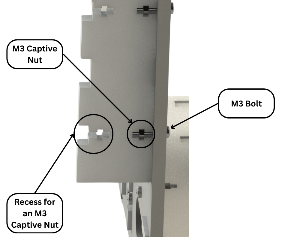
Fig.10
Fig.9 and Fig.10 shows how these acrylic panels are connected together. An M3 bolt through a hole in the main acrylic panel thread into an M3 captive nut held in place in a cut recess in the spacer panel forces the two panels together and locks them in place. This method of connection is used multiple times in this structure and all the others. The M3 nuts are kept from becoming undone by the tight tolerance of the cut recesses that prevent the nuts from turning.
Side Support Structures
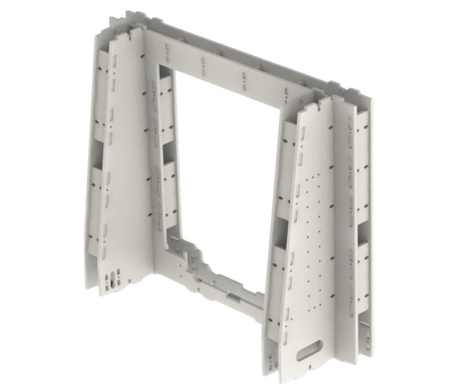
Fig.11
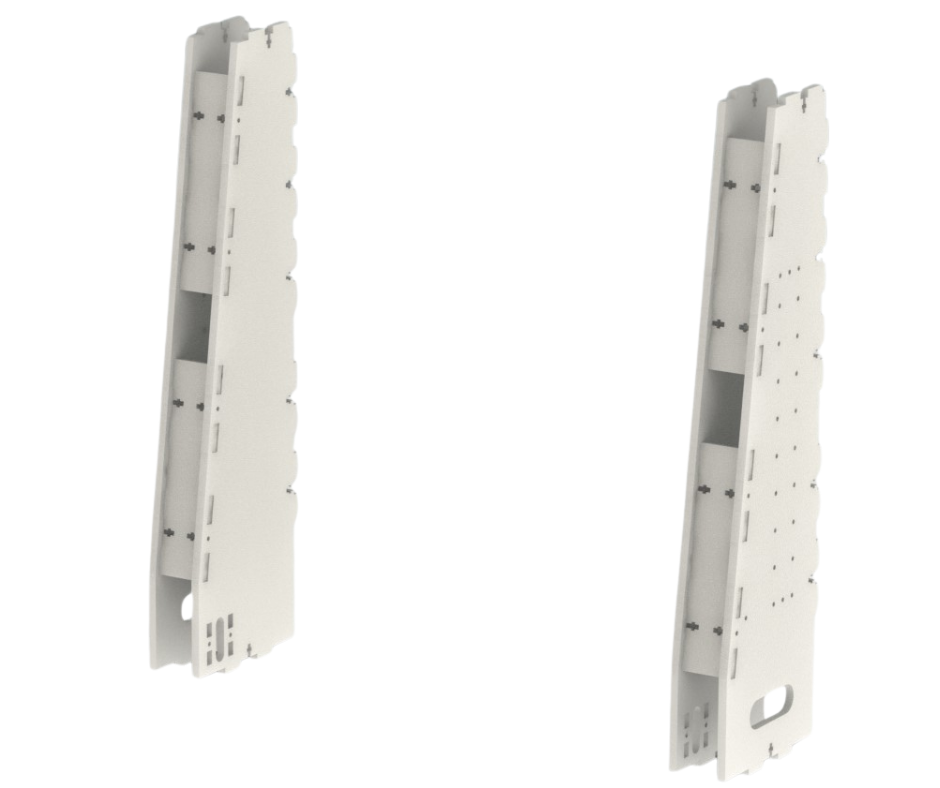
Fig.12
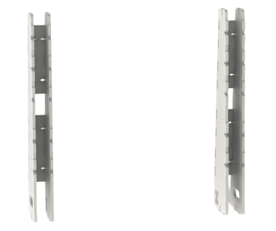
Fig.13
To prevent the central structure from back and forth movement, the side support structures are connected to the central structure and the printer base. These side support structures are shown in Fig.11, Fig.12 and Fig.13. These side support structures are also made from large main panels connected together with smaller spacer panels. These side structures are connected to the central structure as shown in Fig.11 in the same way as shown in Fig.9 and Fig.10. These side support structures also feature mounting points for the printer control and power supply boxes as shown in Fig.14 and Fig.15.
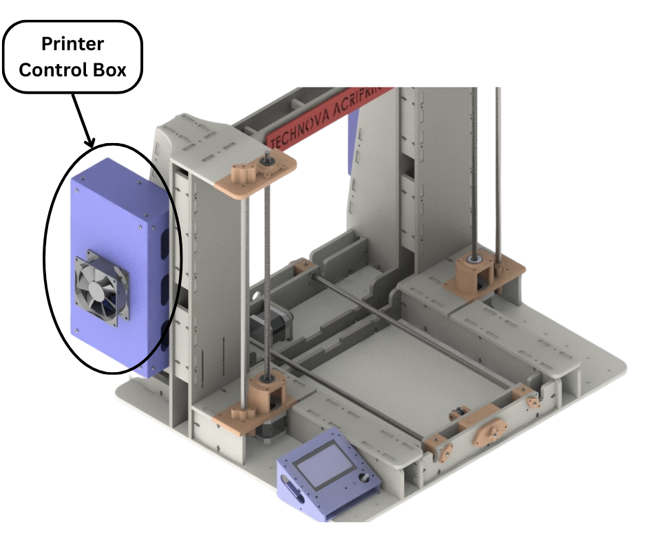
Fig.14
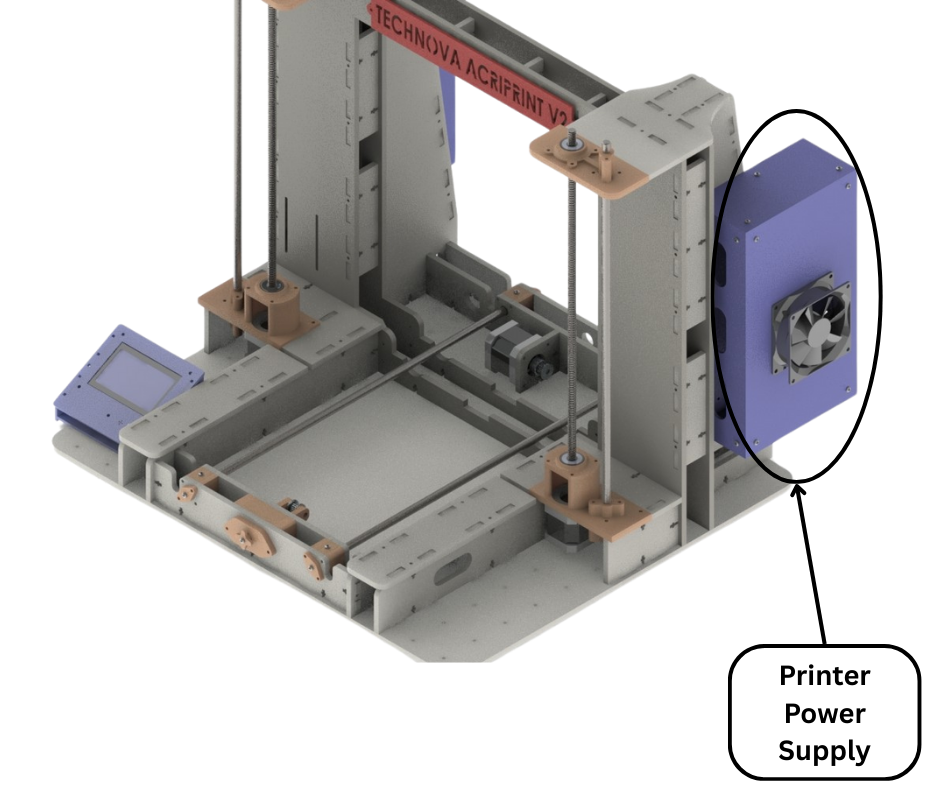
Fig.15
Back structure
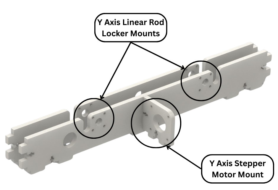
Fig.16
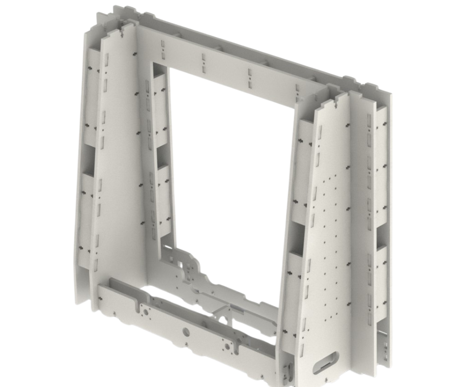
Fig.17
Fig.16 and Fig.17 show the back structure of the printer frame. This structure forms one half of the Y axis Gantry of our 3D printer frame. This structure attaches to the two side support structures and the printer base. This structure has a mount for the Y axis stepper motor. It also has mounts for 3D printed parts that align and hold the Y axis linear rods in place. These are shown in Fig.18.
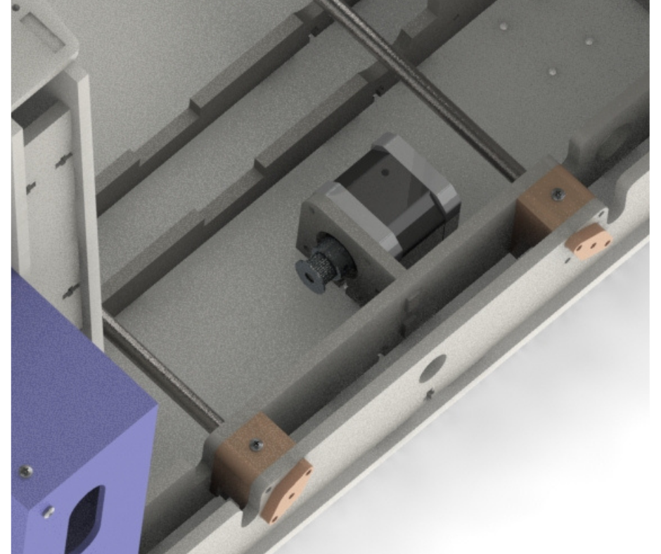
Fig.18
Front structures
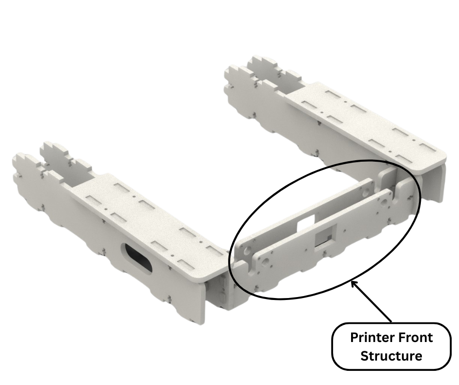
Fig.19
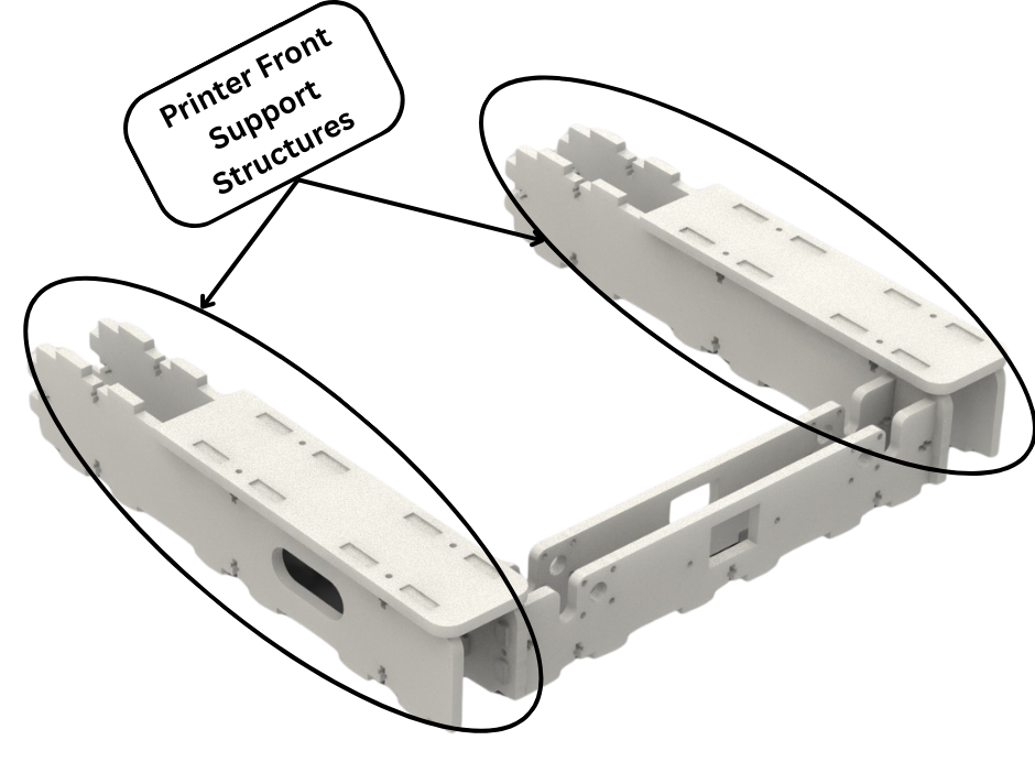
Fig.20
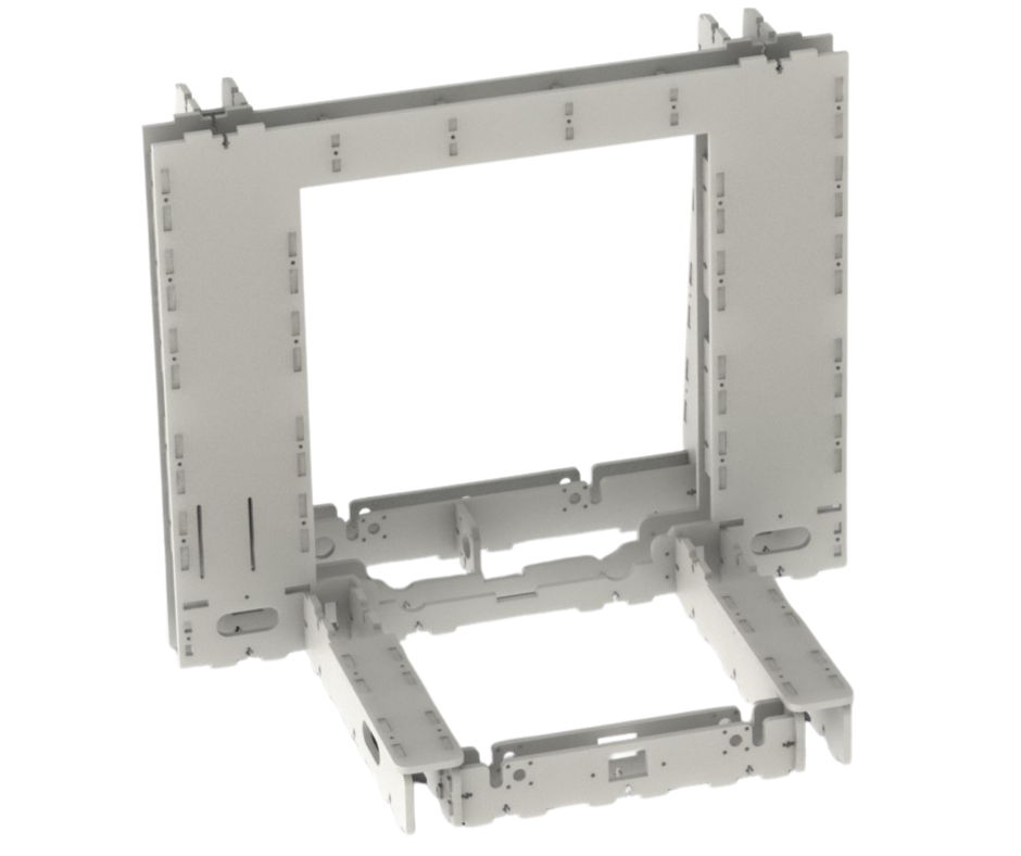
Fig.21
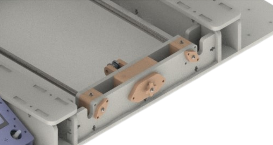
Fig.22
Fig.19, Fig.20 and Fig.21 show the front structures of our 3D printer frame. There is the front structure of the printer frame that forms the other half of the Y axis gantry along with the back structure of the frame as discussed earlier. This structure has mounts for the Y axis belt tensioning mechanism and 3D printed parts that align and hold the Y axis linear rods in place as shown in Fig.22. All these components will be discussed in further detail in another post regarding the Y axis gantry and print bed. Fig.20 highlights the front support structures of our 3d printer frame. These take over the role that the threaded rods performed in version 1 of our 3d printer. The front structure connects to these supports structures which in turn connect to the main central structure as shown in Fig.21. These support structures perfectly align and hold the front structure in place and deter side to side or vertical movement of the front structure.
Z Motor Mounts and Top Panels
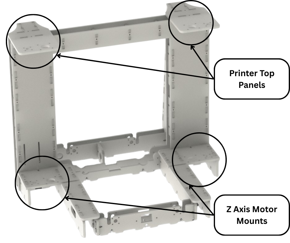
Fig.23
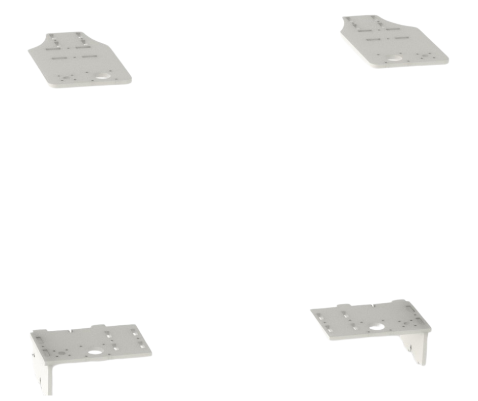
Fig.24
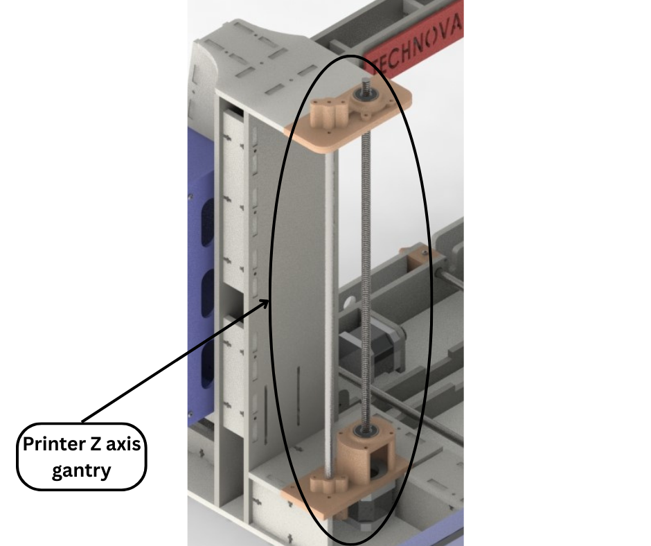
Fig.25
Fig.23 and Fig.24 show the Z axis motor mounts and printer top panels. The motor mounts and top panels form the Z axis gantry of our 3d printer. The left Z axis gantry is shown in Fig.25. The Z axis gantry will be discussed in further detail later in the next post. The Z axis motor mounts connect to the central structure, the front support structures and the base while the printer top panels connect with the central structure and the printer side support structures as shown in Fig.23. All these interconnections serve to increase structural integrity and strength.
Printer Base
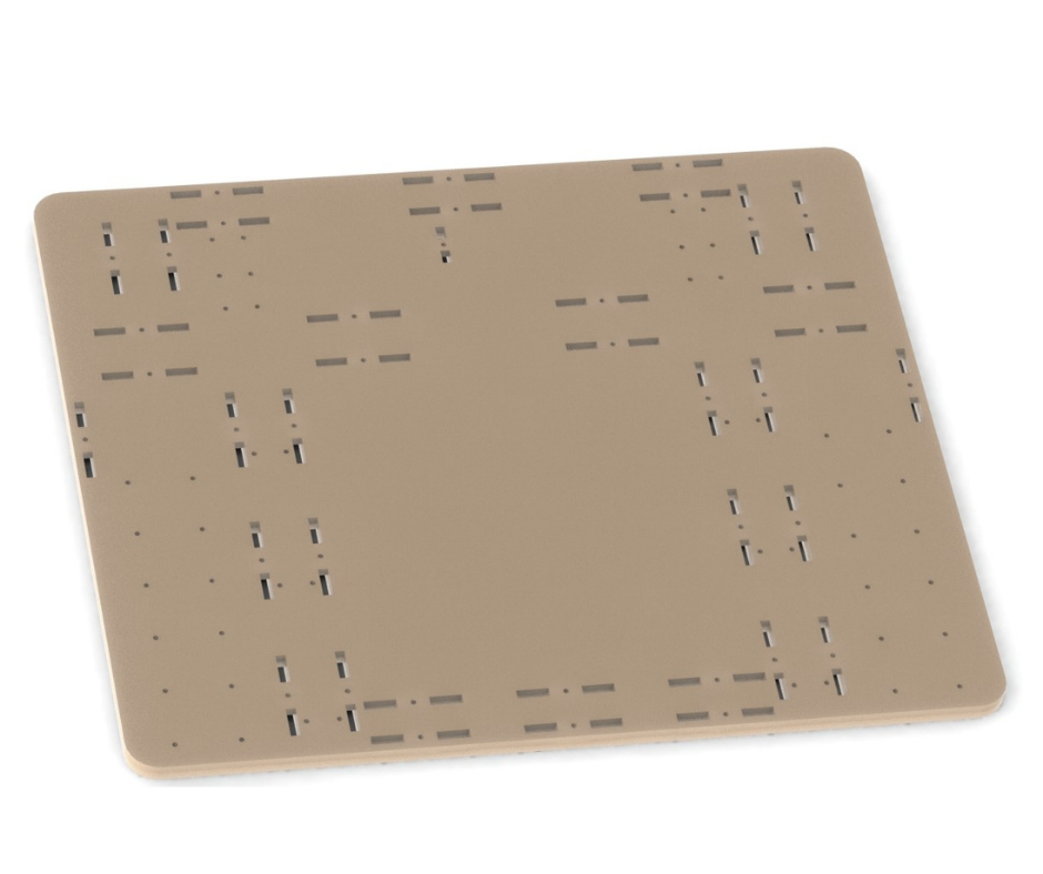
Fig.26
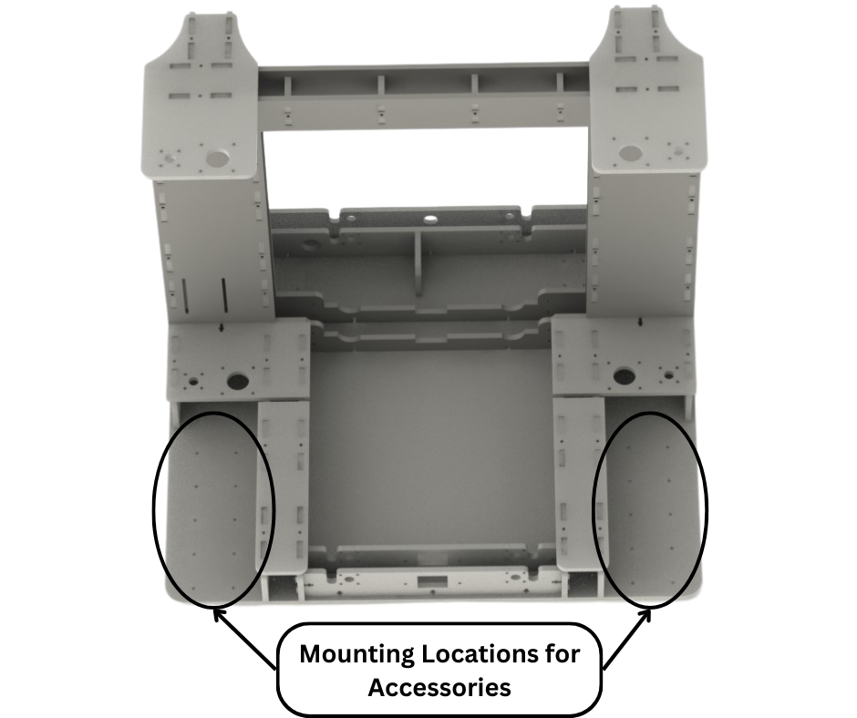
Fig.27
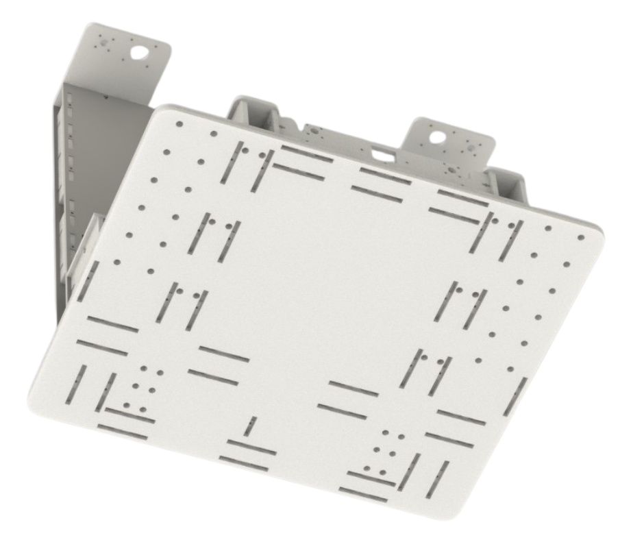
Fig.28
Fig.26, Fig.27 and Fig.28 show the printer base. This structure is made from a 12mm thick acrylic sheet with slots and holes laser cut. This structure connects all the structures discussed previously as shown in Fig.27 and Fig.28. By connecting all the structures together, this base increases the structural strength and integrity of the printer frame. The base also aligns and locks all the different structures discussed earlier in their respective places and prevents shifting or movement whenever the 3d printer is moved around. The printer base also has many additional mounting points for additional peripherals and accessories as shown in Fig.27. We used the left mounting locations to mount the LCD for the 3d printer as shown in Fig.3. In version 1 of our 3d printer the LCD was mounted to the top of the 3d printer as shown in Fig.1. That was an inconvenient location for the LCD because to interact with the LCD and its controls one had to reach the top of the printer while avoiding the moving parts of the printer. In this new design we have mounted the LCD to the front left of the printer and away from all the moving parts. The LCD in this location is easier and more convenient to operate.
Wiring channels
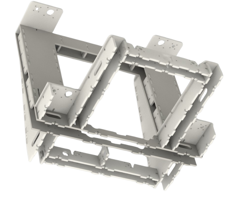
Fig.29
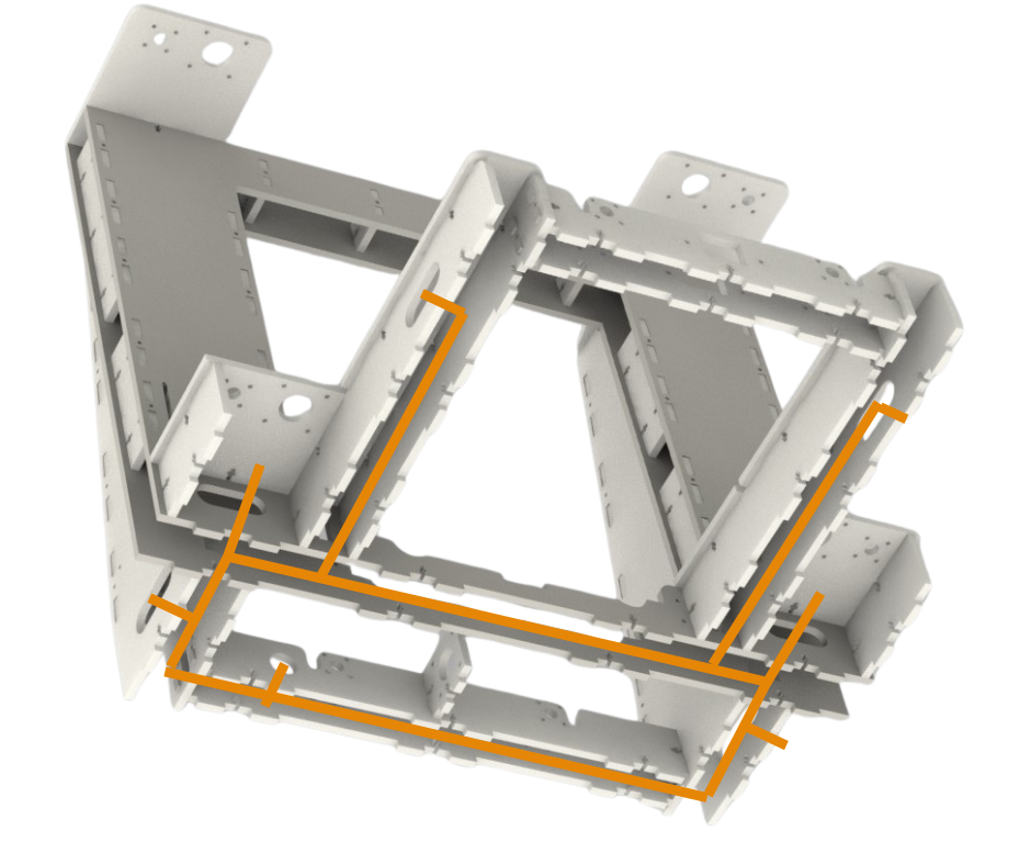
Fig.30
Since all the sub structures of our frame as discussed above are made from large panels joined together by spacers, there are empty spaces in the substructures. This is shown in Fig.29 and highlighted in Fig.30. These empty spaces are an ideal solution to wiring in our 3d printer. A 3d printer has a lot of wiring that needs to be routed from the power supply, LCD, sensors, heaters and all the motors to the control box. In our case it means that wires have to be routed from essentially everywhere to the control box mounted on the left side support structure as shown in Fig.14. The empty spaces within the sub structures of our 3d printer provide a neat and convenient way to route all the wires to our control box. Fig.30 shows how this can be achieved. This way most of the wiring can remain concealed and safe from tampering. Only the wire loom coming from the X axis gantry would be visible and that too only partially.