In this post we will be discussing a major upgrade that we made to the extruder mount that was discussed in an earlier post regarding the X axis of Acriprint version 2.
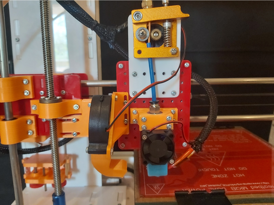
Fig.1
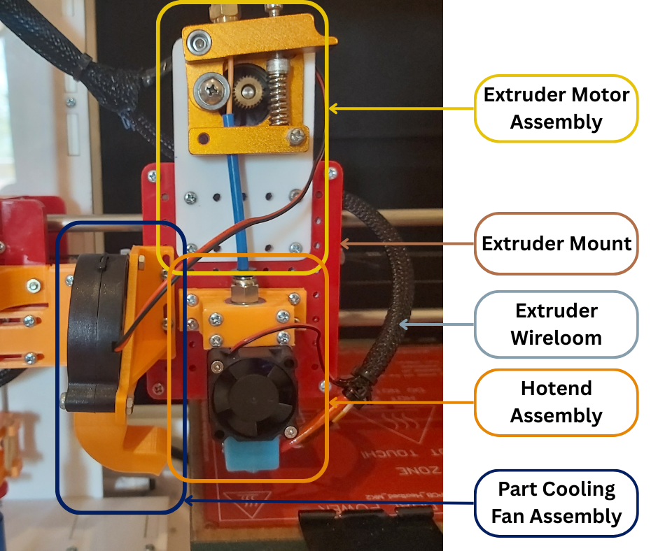
Fig.2
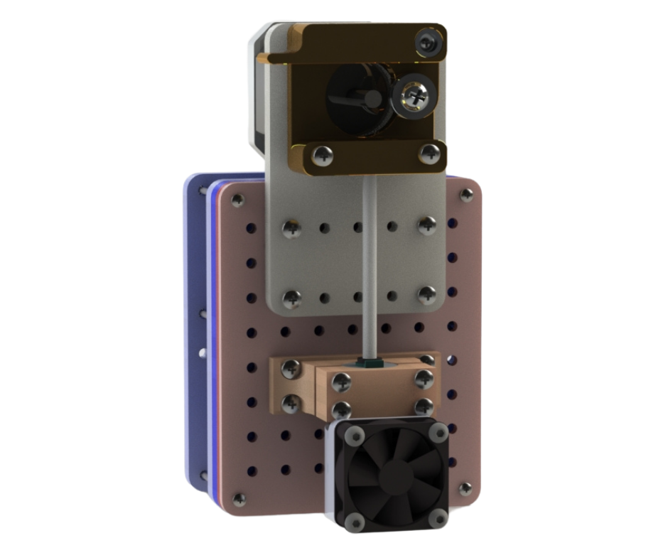
Fig.3
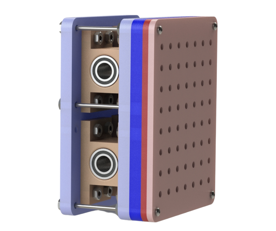
Fig.4
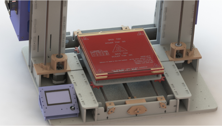
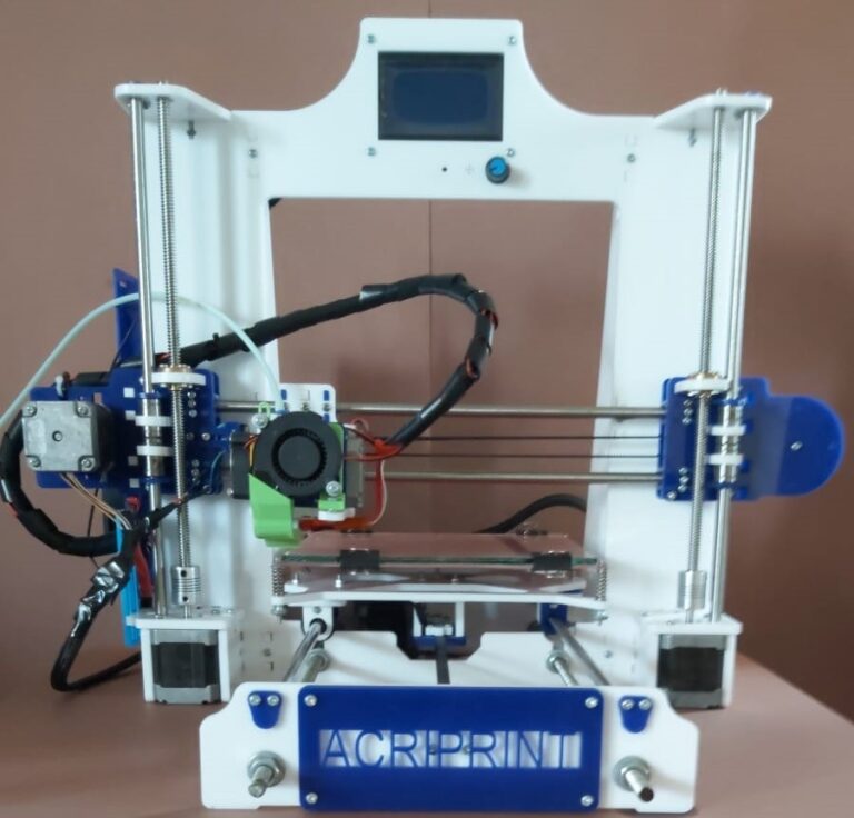
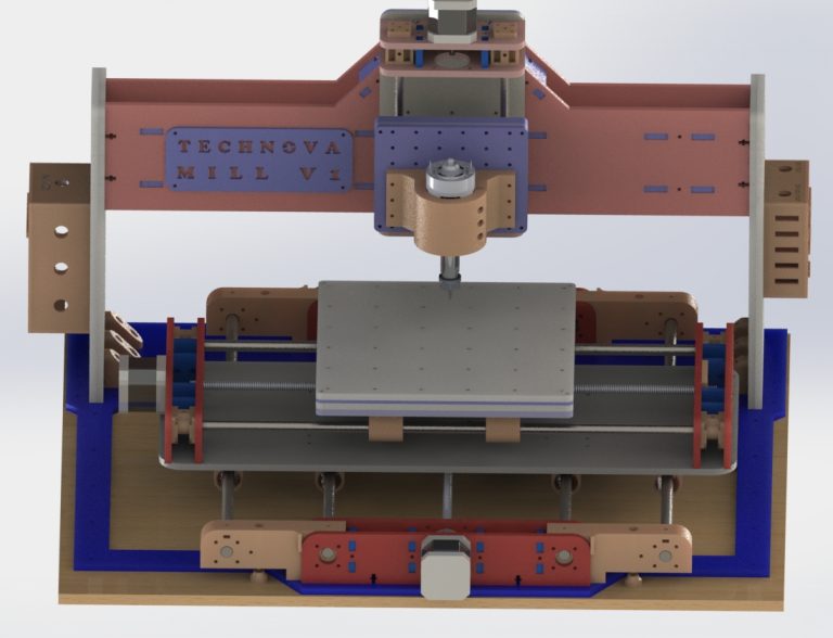
Fig.1 through Fig.4 show the design and implementation of the extruder mount assembly for our version 2 of our 3d printer. As mentioned in our earlier post regarding the extruder mount assembly, we designed this mount to be modular and allow easy mounting of different types of hotends, extruder motors and part cooling fan configurations. Our original configurations can be seen in Fig.2 and Fig.3.
During implementation and use of this design we found out that although mounting components to the extruder mount was easy and trouble free, changing the wiring was not. As can be seen in Fig.2, the wire loom consists of a collection of all the wires coming from the extruder motor, hot-end assembly and part cooling fan. There were no interconnects between the wires from all these components and the final wire loom going to the 3d printer control box. This meant that if we needed to change an electronic component on the extruder assembly, we would need to cut the required wires and solder them to the new component. This had to be done anytime any new component had to be added or an old one replaced.
To resolve this wiring issue and allow for easy connection and disconnection of components modified the design of the existing extruder mount design. We retained the easy mounting feature and front of the existing design. We just replaced the bearing mounts and the back panel of the extruder mount with 3d printed parts. This can be seen in Fig.5 through Fig.7.
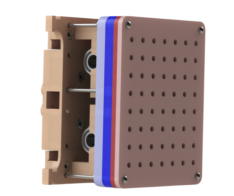
Fig.5
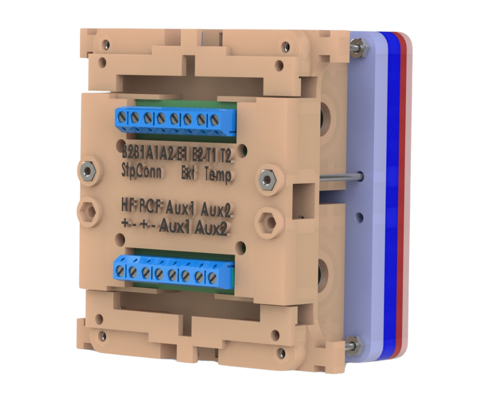
Fig.6
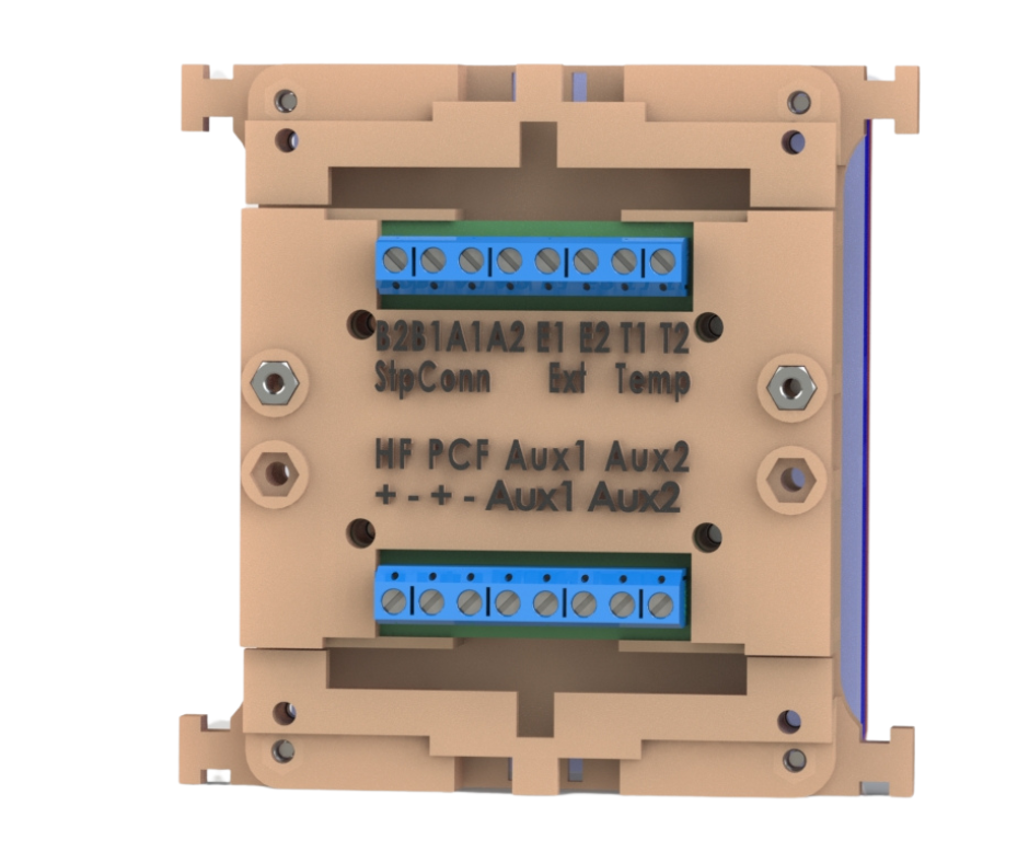
Fig.7
In this upgrade we added electrical terminal blocks to the back of the extruder mount. The wire loom of the extruder mount now connects to these terminal blocks. These terminal blocks now allow electronic components such as sensors, motors, heaters, etc to easily connect to and disconnect from the extruder mount. We have also added extra ports to allow for connection of sensors and/or accessories in the future if need be. Fig.8 through Fig.12 shows the design being put to use in a prototype.
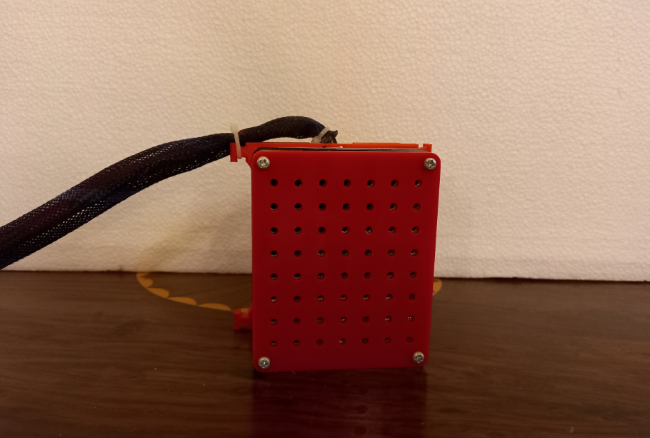
Fig.8
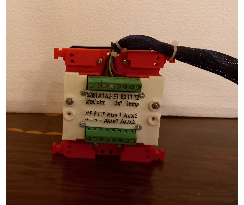
Fig.9
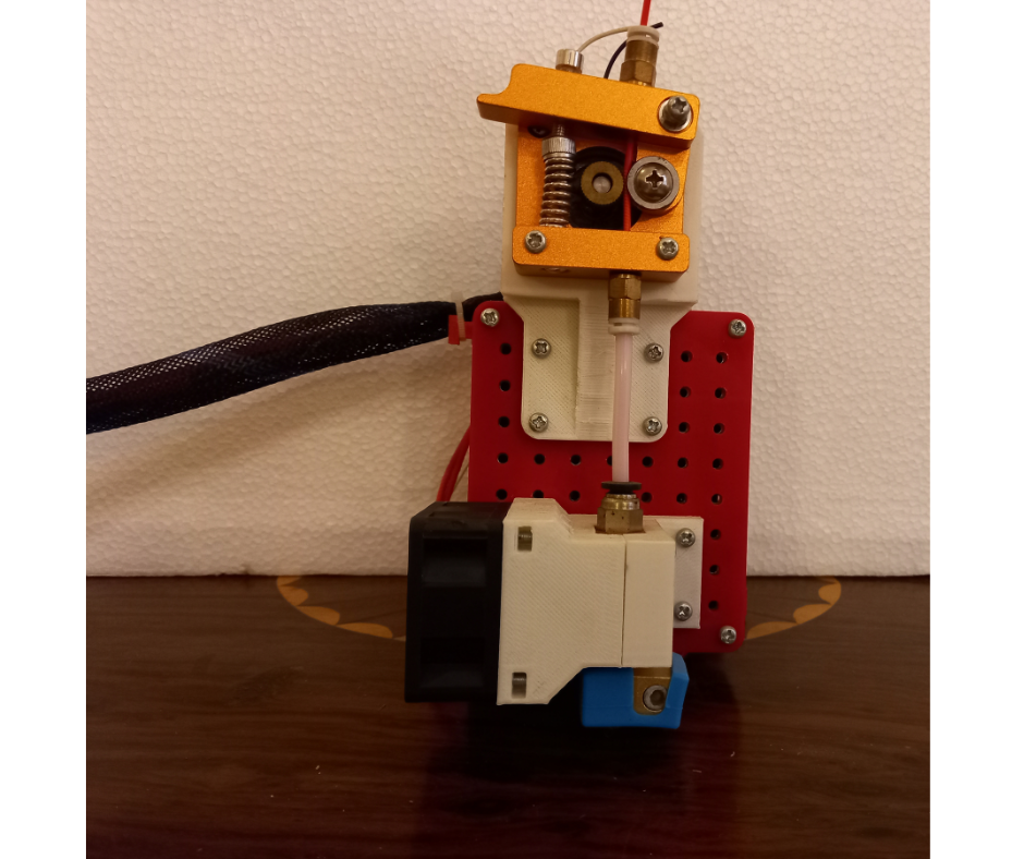
Fig.10
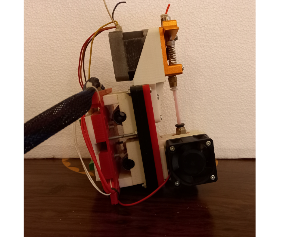
Fig.11
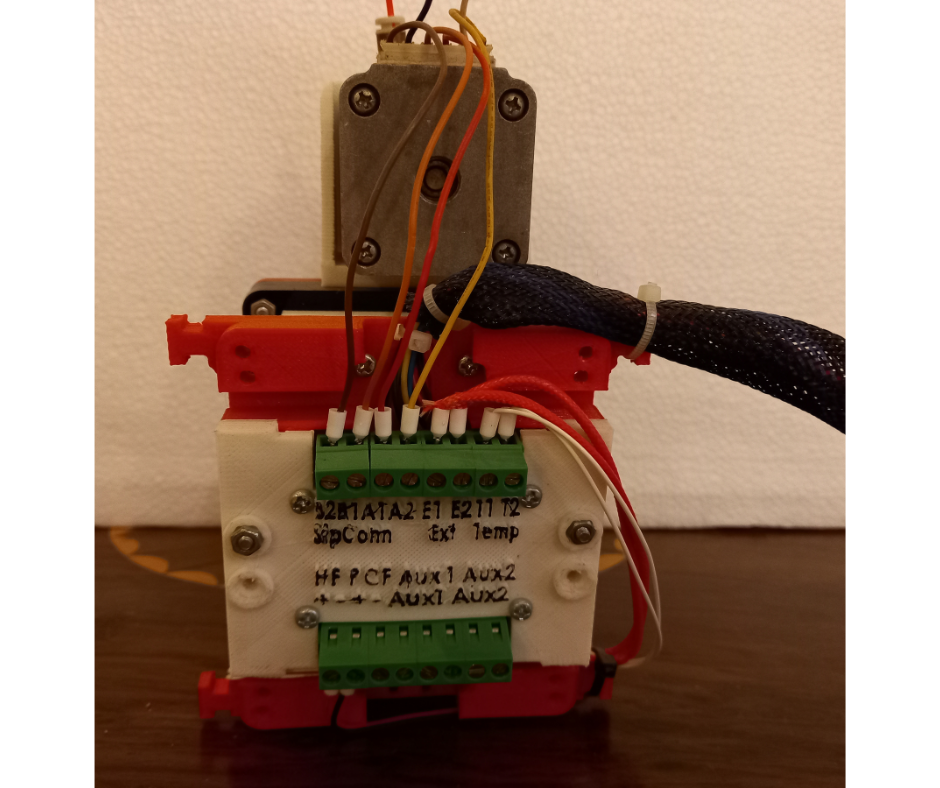
Fig.12
This upgrade has been a much needed ease of use improvement. It has allowed us to rapidly switch between different extruders and test with different part cooling designs and fans without the need for cutting and soldering. We would also like to mention that this wasn’t the first iteration of this design. There were other designs as well for a quick connection system. But this iteration was the one that we adopted after all the testing.