In this post we will discuss in detail the Y axis of our 3D printer and the print bed assembly that moves along the Y axis.
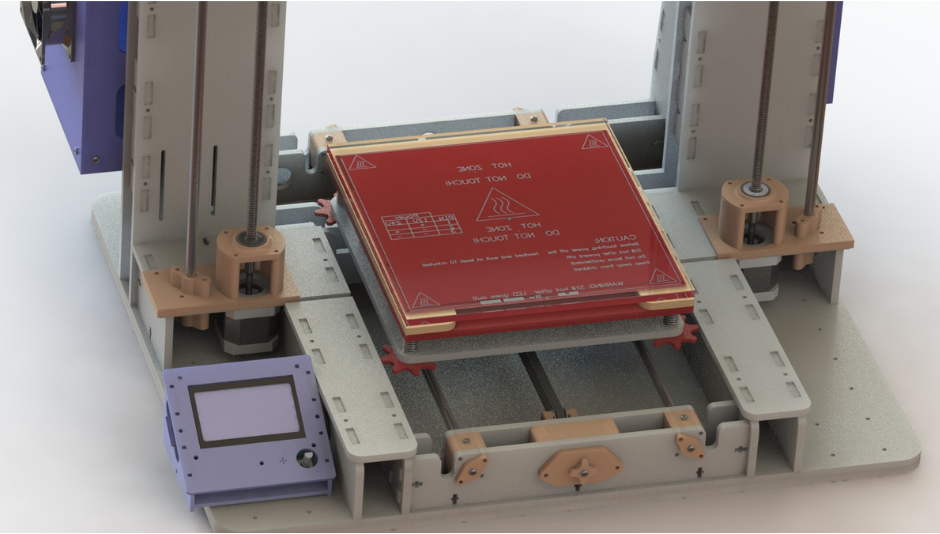
Fig.1
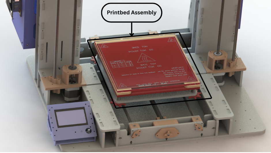
Fig.2
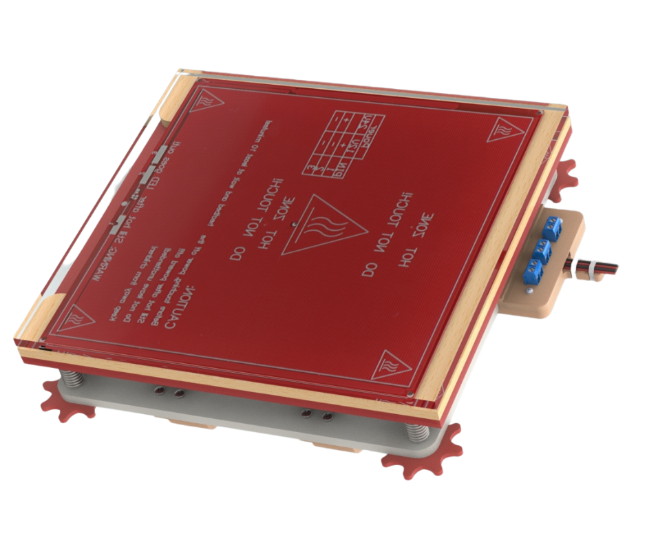
Fig.3
Fig.1 shows our assembled Y axis. The Y axis comprises two main parts. The first part comprises the components that interface with the frame of the printer to form what we call the Y axis Gantry. This will be discussed later on in this post. The second part is the print bed assembly (Fig.2 and Fig.3) that we will discuss now.
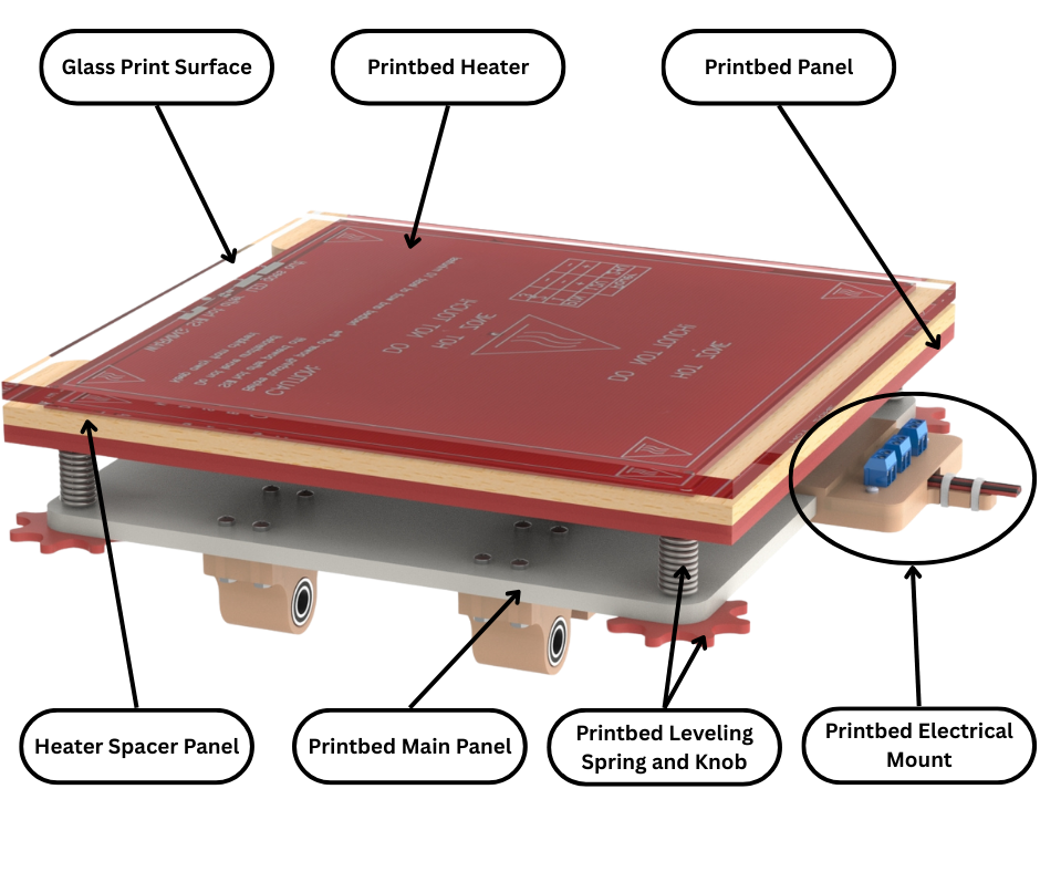
Fig.4
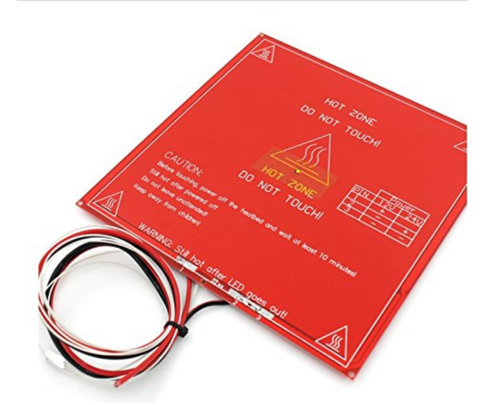
Fig.5
Fig.4 shows a side view of the print bed assembly with all components labelled. We will explain all the different components going from top to bottom. At the top we have the glass print surface. This is the surface over which the extruder of our 3d printer deposits molten plastic to form a 3d print. We have chosen a tempered glass surface because it is resistant to impact and has high tolerance for heat which is essential because this is a heated print bed. The glass also has good adhesion to the 3d printed materials. This means that there is less warpage and low chance of detachment of 3d prints from the print bed. Then we have the heater PCB (Fig.5). This printed circuit board generates heat when voltage is applied to it. It also has a thermistor attached to it which monitors the temperature and relays that information to the 3d printer controller. This way the controller can control the temperature of this heater pcb. This heater pcb provides heat to the glass print surface. Then we have a spacer panel made of cork board or MDF which provides isolation to the panel below it from the heater. The panel below this spacer panel is called the print bed panel and is made from acrylic. This panel, the spacer panel, heater and glass print surface are all sandwiched together using clips. This ensures that the different panels don’t come apart during operation and that there is no gap between the heater pcb and the glass print surface. The print bed panel also has mountings for four M3 bolts that are attached to this panel permanently. These bolts go through the print bed panel and the print bed main panel. Springs are used to provide separation between the print bed main panel and the heater and glass surface ‘sandwich’ above. To compress and decompress these springs, bed leveling knobs are installed on each of the bolts of the print bed panel. When any of the knobs are turned clockwise, the corresponding spring is compressed and vice versa. Compressing or decompressing these springs allows the print bed panel and consequently the glass print surface to be tilted to some degree relative to the print bed main panel. This is done to level the print bed.
Fig.8 highlights the need for bed leveling. When 3D printing we want our print surface to be parallel to the X axis because the extruder nozzle moves in the X axis. If our print surface is not parallel then issues depicted in Fig.8 happens and in most cases leads to print failure. To make our print surface parallel to the X axis, an iterative process of bed leveling is used. This process involves moving the extruder nozzle to each corner of the print bed and adjusting the bed leveling knobs which will tilt the glass print surface such that there is only enough gap between the glass print surface and the nozzle to slip a piece of paper in between. This process is repeated multiple times until the gap between the nozzle and print bed is consistent at all four corners of the print bed.
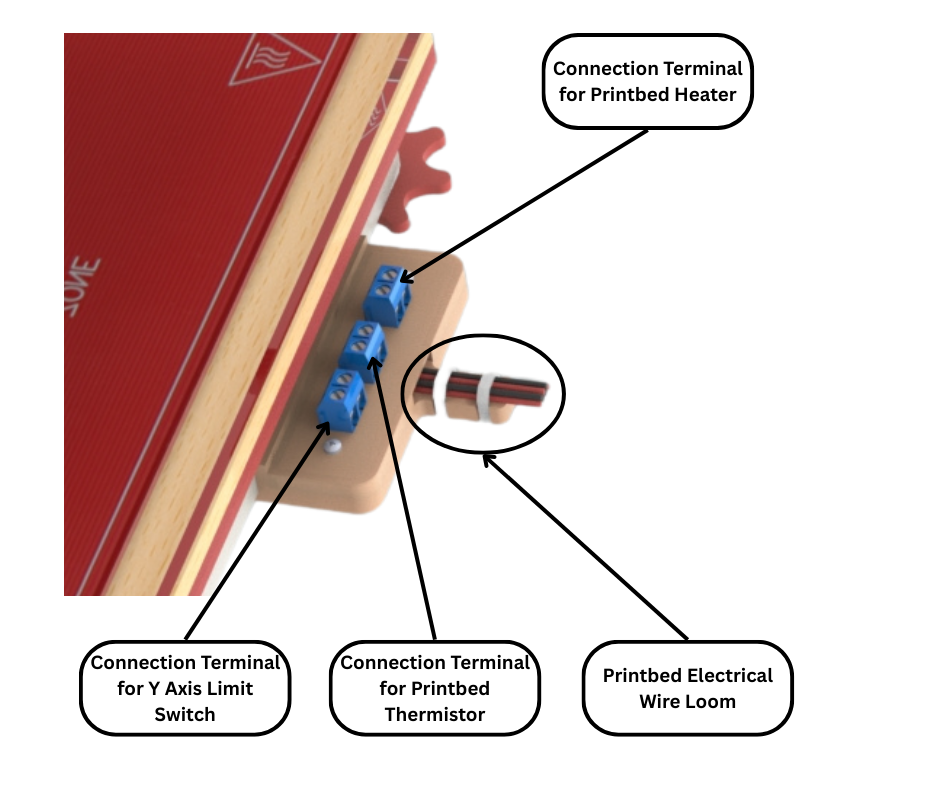
Fig.6
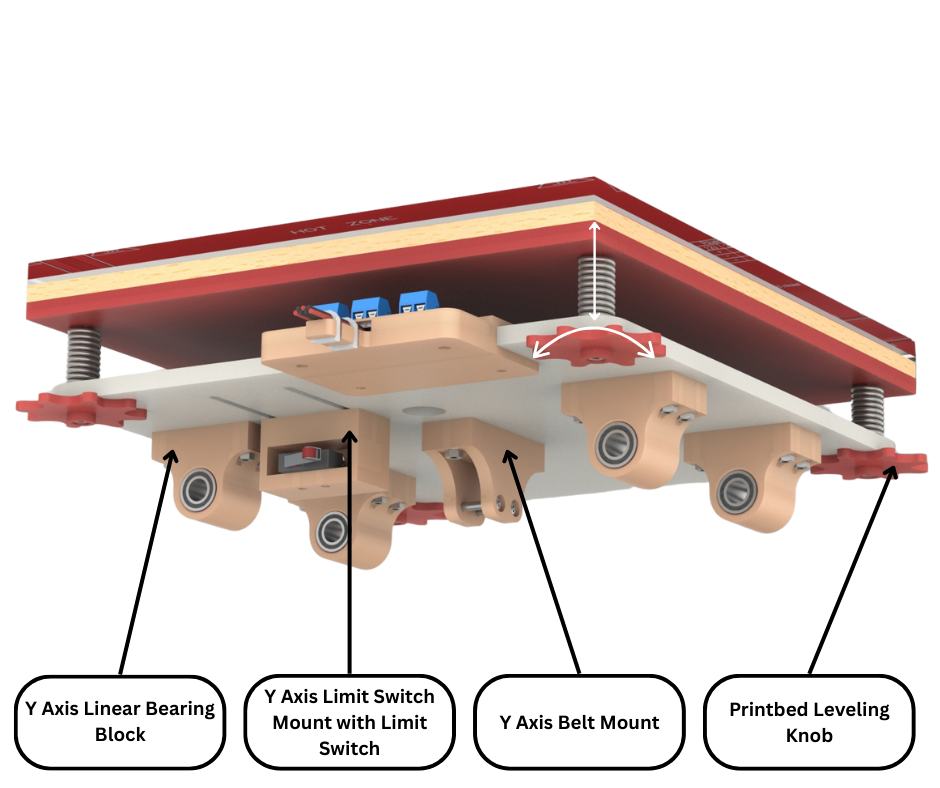
Fig.7
As can be seen in Fig.4 the print bed main panel also has an 3d printed electrical connections panel mounted to it. This is more clearly labelled in Fig.6. This electrical panel has terminals to which the Y axis limit switch (discussed later), print bed heater and thermistor can be connected to. This panel allows us to replace or upgrade any of the aforementioned components easily without having to solder or desolder. The wires from this panel form a print bed wire loom that is routed through the frame of our 3d printed to the control box and connected to our printer controller.
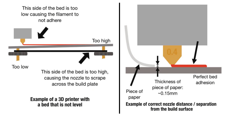
Fig.8
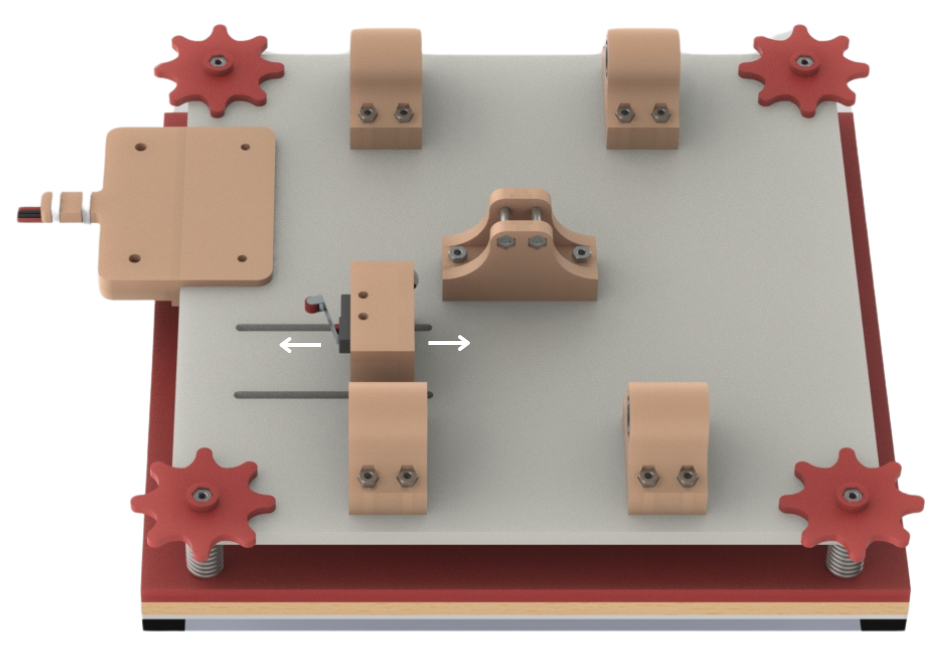
Fig.9
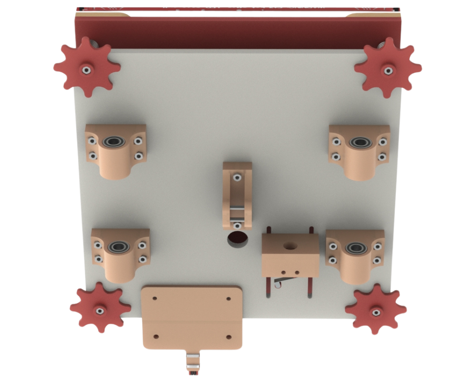
Fig.10
Fig.7, Fig.9 and Fig.10 shows the underside of our print bed assembly. There are four linear bearing blocks bolted to the underside of the print bed main panel. These 3d printed bearing blocks each have an LM8UU linear bearing press fit into it. These linear bearings are used to move along the Y axis linear rods.
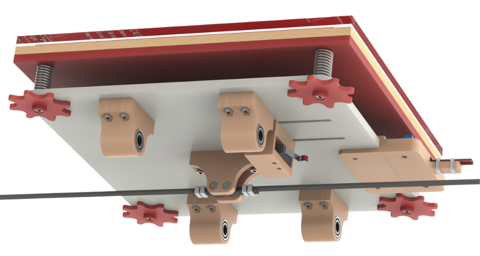
Fig.11
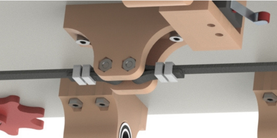
Fig.12
At the center of the print bed main panel a 3d printed Y axis belt mount is also bolted to the underside of the print bed main panel. The ends of the Y axis belt that is used to move this print bed assembly along the Y axis are attached to this component. As can be seen in Fig.11 and Fig.12 the free ends of the Y axis belt are looped around the bolts in the belt mount and then secured using zip ties.
Fig.7 also shows a 3d printed mount for the Y axis limit switch which is attached to this mount. This mount is attached to the underside of the print bed main panel such that it can be adjusted as shown in Fig.9. To move the mount along the slots in the print bed main panel, bolts holding the mount to the main panel are loosened and the mount is moved along the slots to the desired position. Then the bolts holding the limit switch mount to the print bed main panel are tightened to lock the mount in place. The reason behind adding this adjustability will be discussed later on in this post.
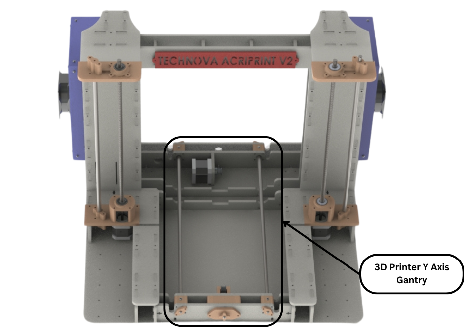
Fig.13
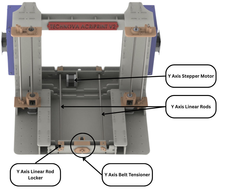
Fig.14
Now we will discuss the Y axis gantry on which the whole print bed assembly is mounted. Fig.13 and Fig.14 show the different components that make up the Y axis gantry. Most of these components are 3d printed and mounted to the main frame of the 3d printer. As we mentioned before, the print bed assembly mounts onto the linear rods shown in Fig.14 using the linear bearing and moves along the linear rods in the Y axis. The actual force needed to move this print bed assembly is provided by the Y axis stepper motor shown in Fig.14. The force is transmitted through the Y axis belt that is connected to the print bed assembly as discussed earlier. How this belt is attached to the motor will be discussed later on in this post.
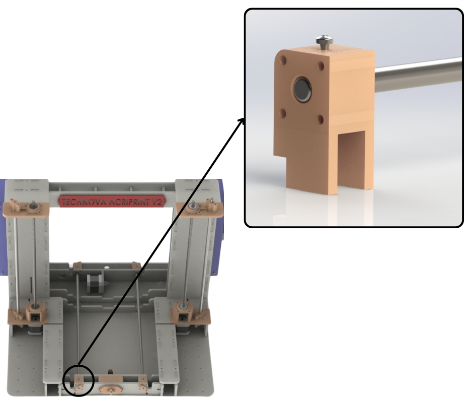
Fig.15
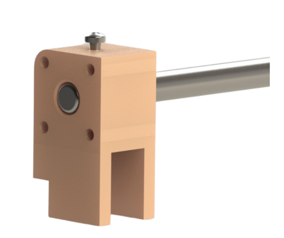
Fig.16
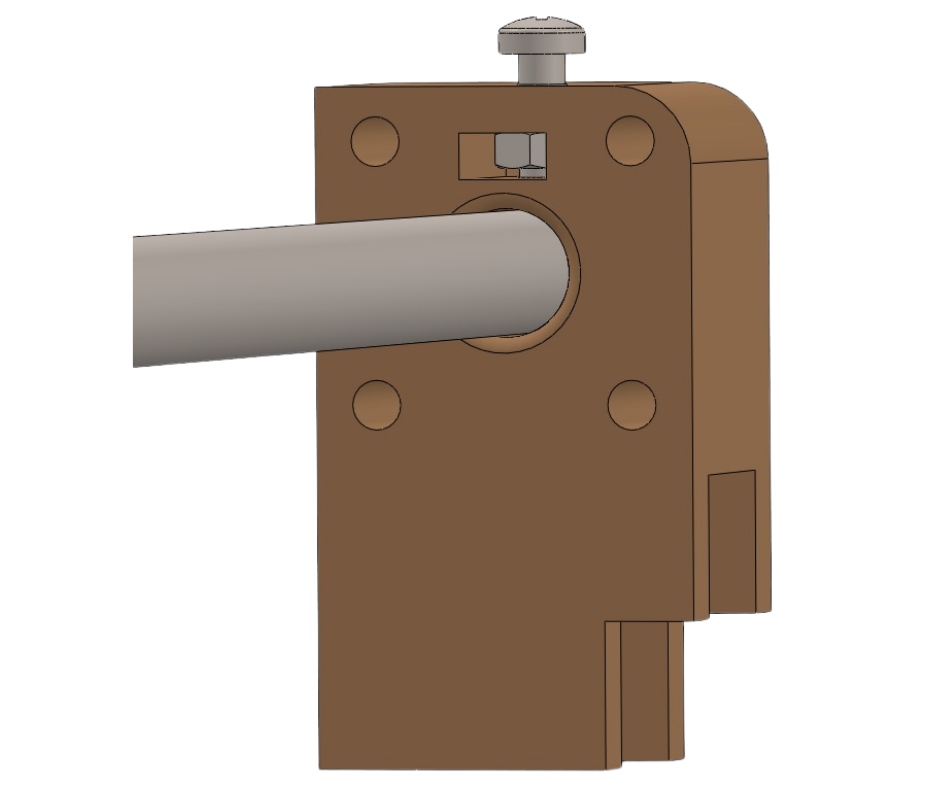
Fig.17
To hold the Y axis linear rods (Fig.14) in their place and prevent them from shifting during printer operation, we have four 3d printed linear rod lockers installed in the frame of the printer. Fig.15 highlights one of these rod lockers. These are installed in the front and back structures of the printer frame as discussed in an earlier post. These structures are part of the Y axis of the printer. These rod lockers are installed between the two panels of the back and front structures of the frame. These rod lockers are attached to the back and front structures using bolts. Once installed the linear rods are inserted into these rod lockers such that each linear rod goes through both the rod locker in the front structure and the back structure as well. As can be seen in Fig.16 and Fig.17 there is an M3 bolt that goes in the top of each rod locker and through an M3 captive nut through to the linear rod in the center. Once the Y axis linear rods are inserted and are in their correct places, the bolts on top of each rod locker are tightened. When tightened these bolts push against the linear rods and prevent them from moving, thereby locking them in place.
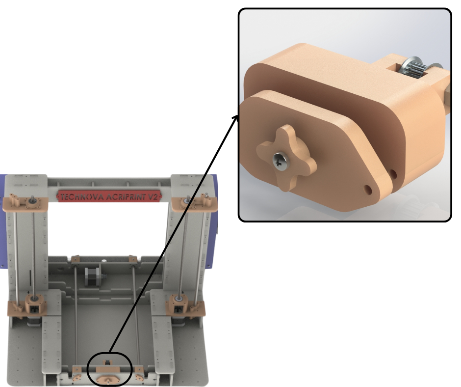
Fig.18
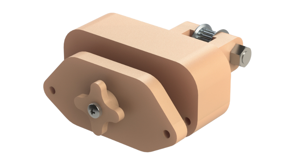
Fig.19
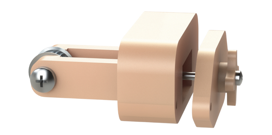
Fig.20
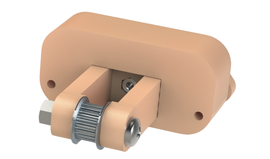
Fig.21
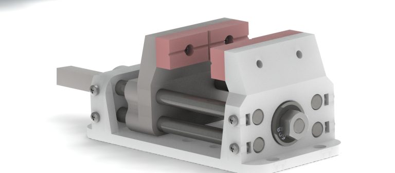
Fig.18 to Fig.21 shows our Y axis belt tensioning system. This is another upgrade that version 2 of our printer has that makes operation of this machine more user friendly and convenient. This belt tensioning system is installed in the front structure of the frame of the 3d printer in the same way as the rod lockers were installed. The tensioning system consists of three parts. There is the tensioning arm that has a GT2 idler pulley installed at its end. Then there is the central part that acts as a guide for the tensioning arm so that it can only move in one direction. This central part of the tensioning system is installed between the two main panels of the front structure of the frame of the 3d printer. The final part of the tensioning system is the front panel with the tensioning knob. This knob is attached to an M3 bolt that goes through the front panel and the central part of the tensioning system to the tensioning arm where it interfaces with a captive nut as shown in Fig.21. When the tensioning knob is turned, the bolt also turns and either pulls the tensioning arm towards the front panel of the tensioning system or pushes the tensioning arm away depending on the direction of turning of the tensioning knob. This action either pulls the Y axis belt loop taut or loosens it.
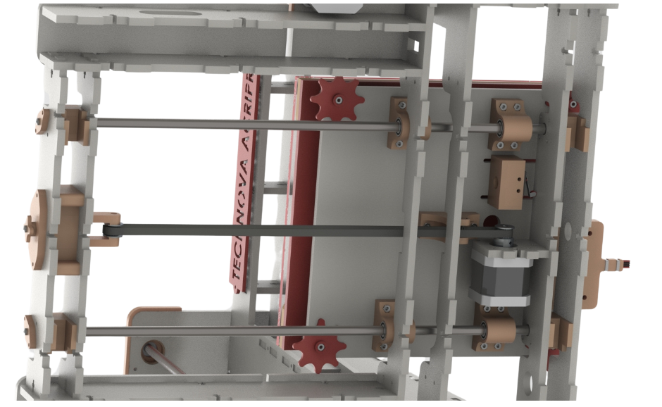
Fig.22
Fig.22 shows the Y axis of the printer from below with the base removed. This clearly shows the Y axis belt loop. The open ends of the Y axis belt are secured to the belt mount on the print bed assembly as discussed earlier. The Y axis belt then loops around the pulley installed on the Y axis stepper motor and also loops around the idler pulley installed on the tensioning arm of the Y axis belt tensioning system. This forms a closed loop belt system where when the y axis stepper motor pulley turns it either pulls the print bed assembly towards itself or it pulls the belt around the idler pulley and moves the print bed assembly away from itself. The Y axis tensioning system ensures that the Y axis belt loop remains taut and that there is no slack in the loop as it would lead to the belt slipping over the pulleys and skipping steps which would cause layer shifting issues in the resulting 3d prints.
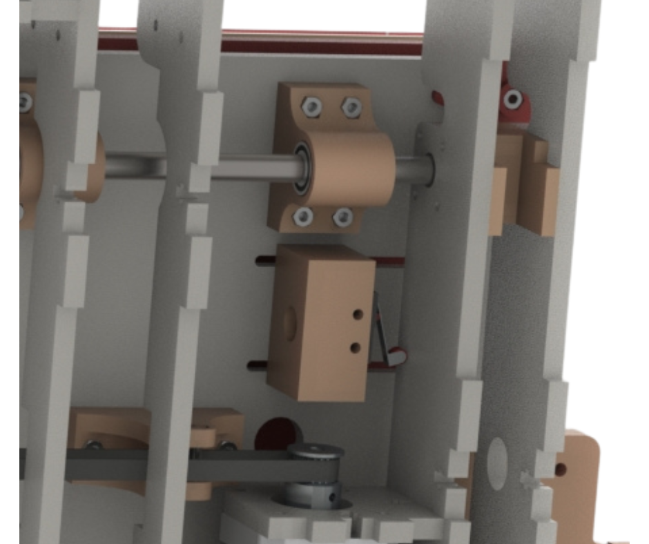
Fig.23
Fig.23 highlights how the Y axis limits switch operates. The endstop for the Y axis when the limit switch mounted on the underside of the print bed assembly touches the back structure of the frame of our 3d printer. This activates the limits switch and lets the controller know that the Y axis endstop has been reached. The controller then knows that the zero position in the Y axis has been reached. This position is the Y axis origin point which along with the X axis origin is the bottom left corner of the print bed print surface. Making the limit switch mount adjustable (as described before) allows us to shift this starting Y axis position backwards or forwards. This gives us some leeway when upgrading components such as extruders or even changing the entire design of the extruder or print bed assemblies. Changing these might require shifting the existing origin points of the X and Y axis. The adjustability of the Y axis limit switch mount gives us the ability to shift the Y axis origin point.