In this post we will be discussing the Z axis gantry of version 2 of our custom designed 3D printer.
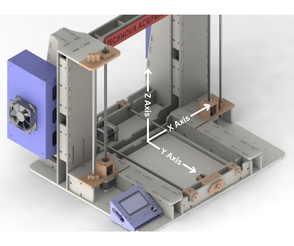
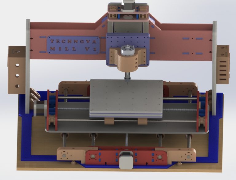
Fig.1
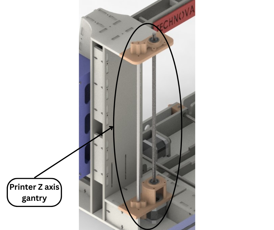
Fig.1 shows the coordinate system of our 3D printer. The Z axis is the axis that is vertical to the base of the printer. Fig.2 shows the Z axis gantry which consists of two halves, namely the left and right Z gantry. Both the left and the right Z gantries are the same in terms of principles of operation and physical construction. So we will focus our discussion on the left Z gantry which will also be valid for the right side.
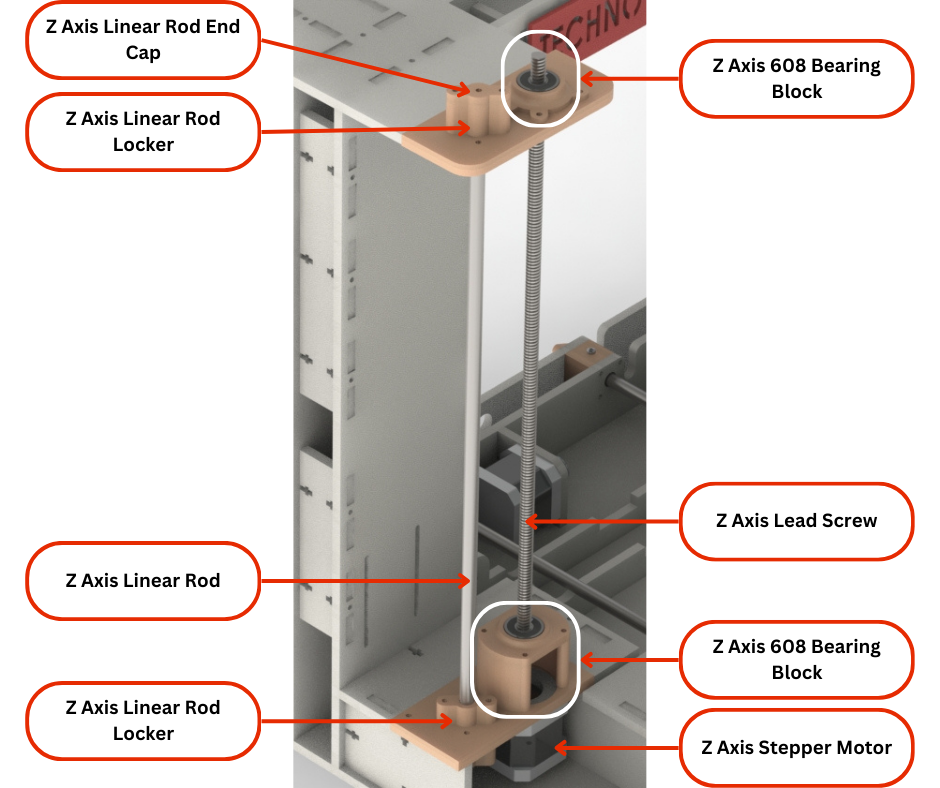
Fig.2
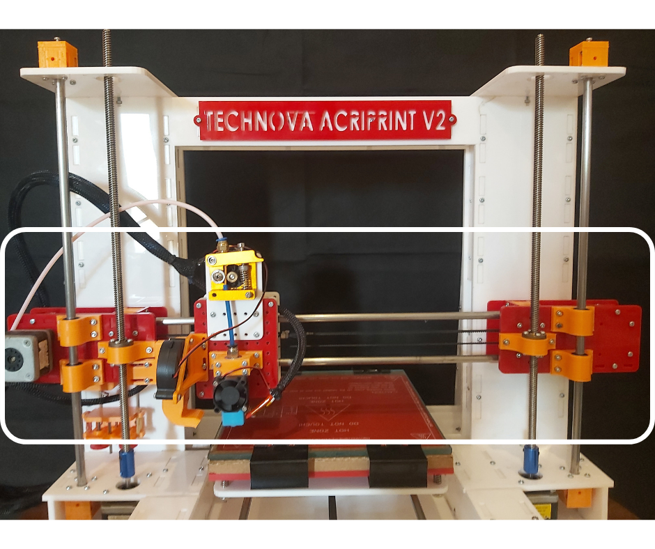
Fig.3
Fig.2 shows the main components of the Z gantry. We will now discuss each of them briefly. Like all other cartesian 3d printers, the Z axis serves to move the entire X axis gantry vertically as can be seen enclosed in the white rectangle in Fig.3. Now the X gantry uses Linear rods and threaded rods of the Z axis gantry to move up or down.
The Z axis linear rods mentioned in Fig.2 are 8mm rod smooth stainless steel rods. These rods are held in place by two 3D printed linear rod lockers that are installed on the Z axis motor mounts and the printer top panels as seen in Fig.2. These rod lockers essentially align and hold the linear rods in place so that they don’t move around during printer operation.
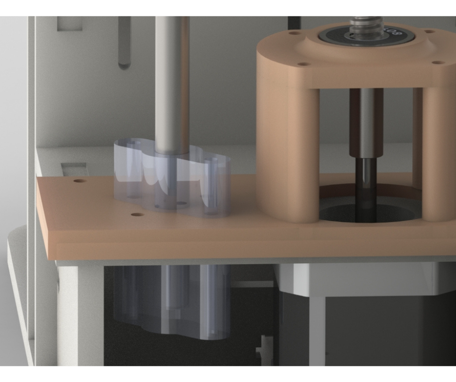
Fig.4
Each Z axis linear rod is installed into the rod locker installed on the top panel from the top. The linear rod is then fed in from the top until it reaches the linear rod locker installed on the Z axis motor mount. The linear rod is fed from the top until the rod is completely seated in the bottom rod locker as shown in Fig.4. Then the linear rod locker end cap is installed on the top linear rod locker to prevent the rod from shifting vertically during printer operation.
Fig,5
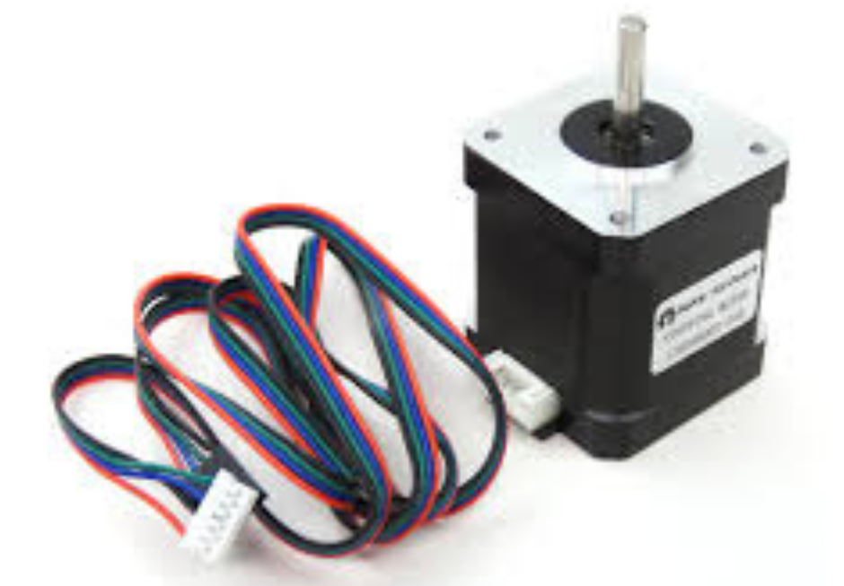
Fig.6
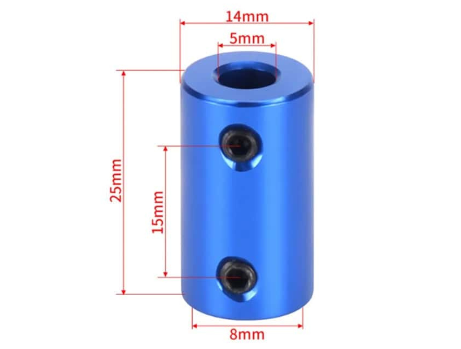
Fig.7
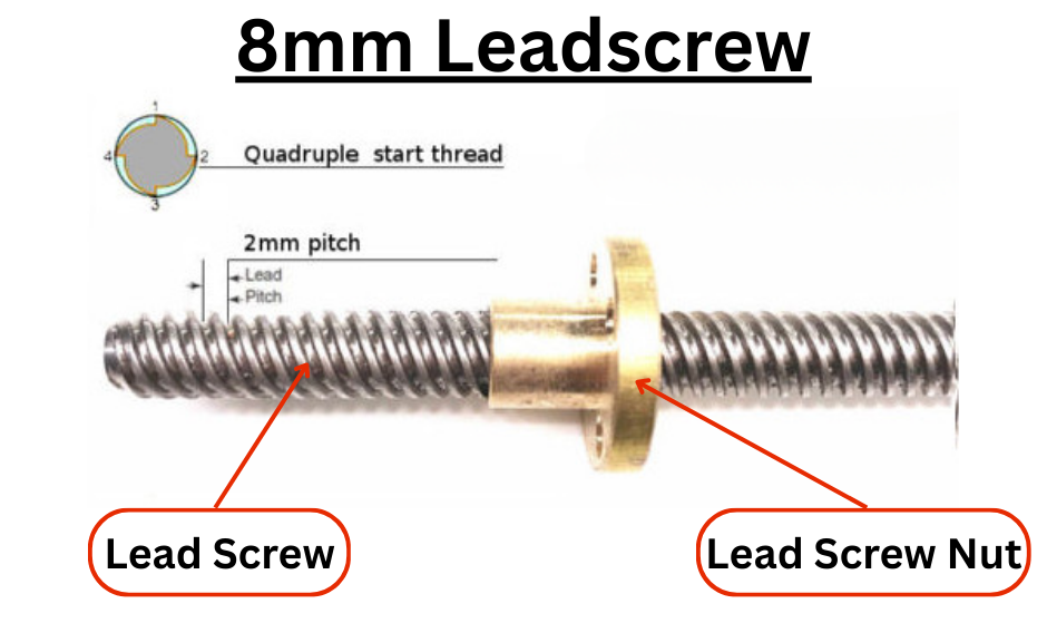
The linear rods of the Z gantry are there to guide the X gantry vertically and to hold the X gantry in place while allowing vertical movements. The task of moving the X gantry up or down is done by the Z axis stepper motors and the threaded rod that each of them are connected to. As shown in Fig.5 each leadscrew is coupled to a leadcrew nut. As the leadscrew turns the leadscrew nut either moves up or down depending on the direction of turning of the leadscrew. A leadscrew nut is attached to either end of the X axis gantry. Therefore when the two leadscrews of the Z axis gantry turn in the same direction and by the same amount, then the X axis gantry will either move up or down the Z gantry depending on the direction of rotation of the leadscrews. To turn each leadscrew a stepper motor is used. Z axis gantry uses two Nema17 stepper motors shown in Fig.6. Each stepper motor is mounted to the Z axis motor mounts shown in Fig.2. Each leadscrew is installed into the Z gantry from the top. Each leadscrew is fed from the top, first through the top bearing block and then through the bottom bearing block. Each leadscrew is then coupled to a Z axis stepper motor by using a coupler shown in Fig.7.
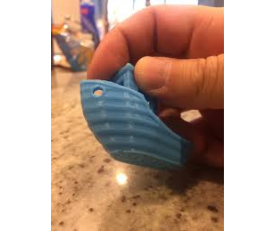
Fig.8
The bearing blocks on the Z axis motor mounts and the top panels are one of the many improvements over version 1 of our printer. In version 1 if either leadscrew was not coupled with its respective stepper correctly, then the axis of the leadscrew would not be inline with the rotational axis of the stepper motor. This would cause the leadscrew to wobble ever so slightly when rotating. This would cause the end of the X axis gantry to shift or twist slightly because the leadscrew nut was attached to it. This resulted in wave-like artifacts to appear in the part being 3D printed as shown in Fig.8. To fix this issue in version 2 of our 3d printer, we have constrained the leadscrews by using 3d printed bearing blocks. The blocks hold the leadscrew in place and concentric with the shafts of the stepper motor. This setup makes sure that the leadscrew does not wobble when turning. The 608 bearings in the bearing blocks allow for smooth rotation while preventing radial movements of the leadscrews. This little upgrade has drastically improved the quality of the prints.