In this post we will be discussing the X axis of version 2 of our Acriprint 3d printer.
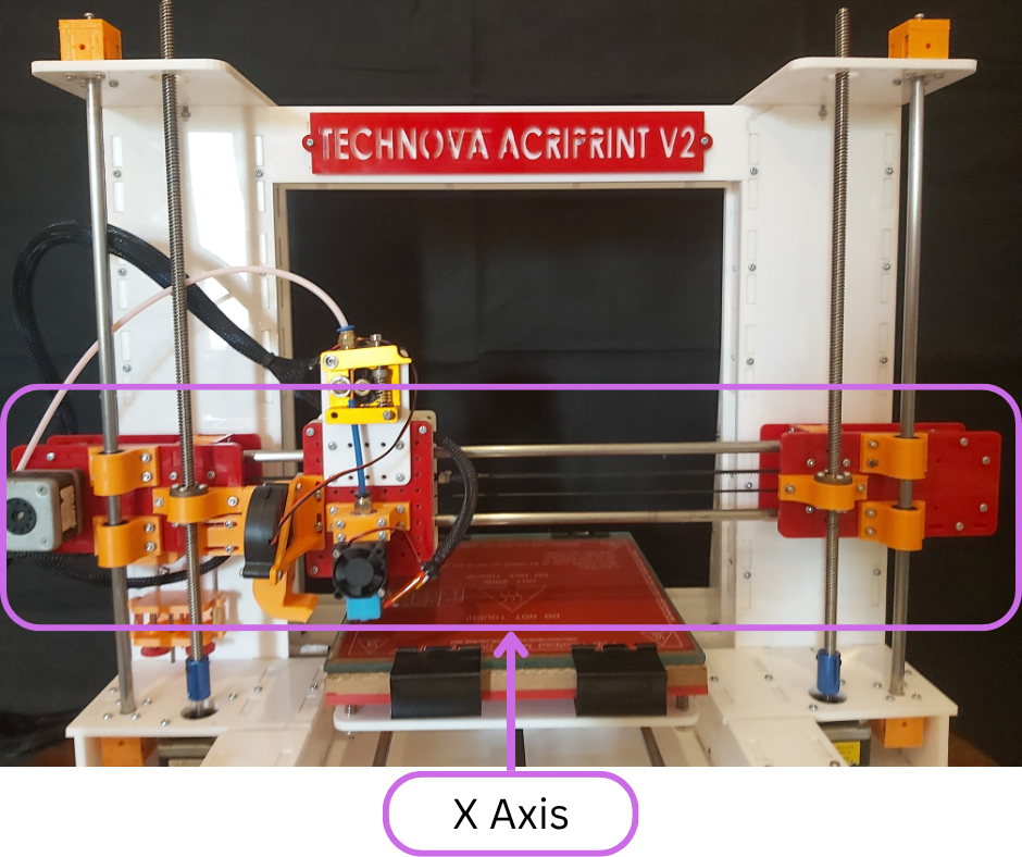
Fig.1
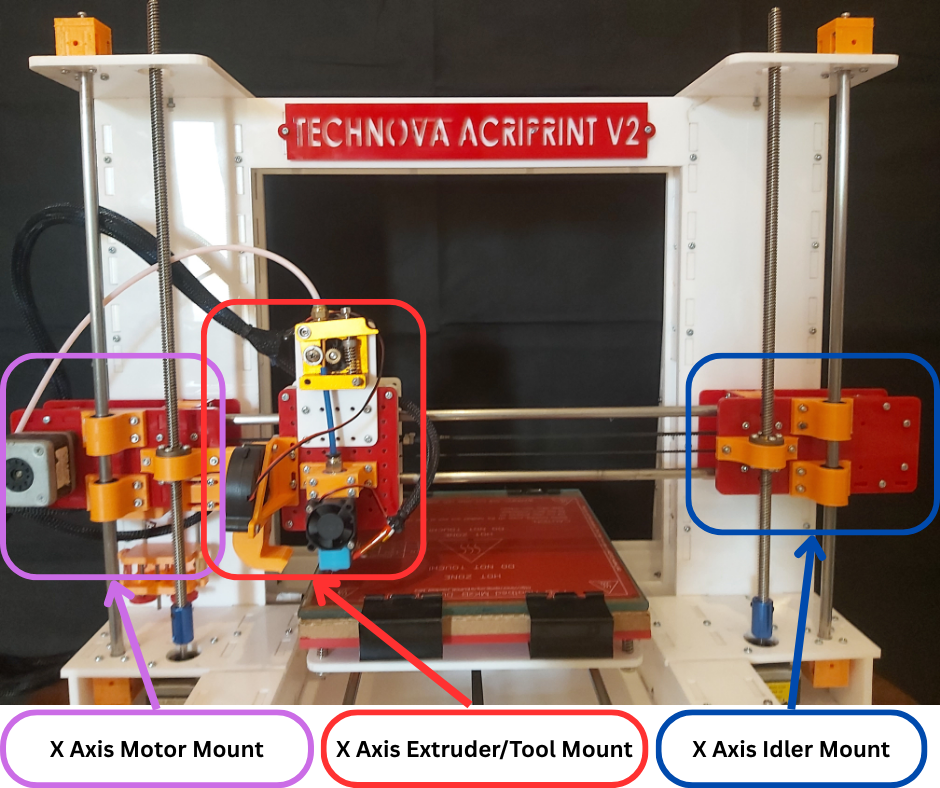
Fig.2
Fig.1 highlights the X axis of our 3d printer. Fig.2 shows that the X axis of our 3d printer consists of 3 main assemblies. Namely the X axis Motor mount, the X axis Extruder/Tool mount and the X axis Idler mount. We will now discuss each of these in more detail.
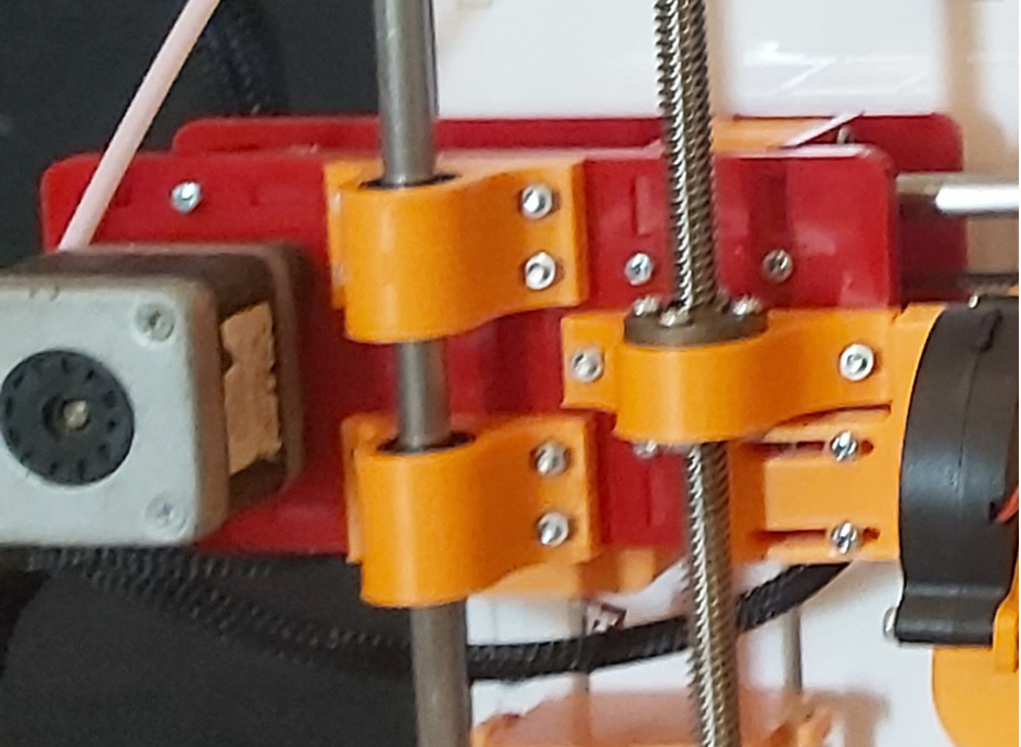
Fig.3
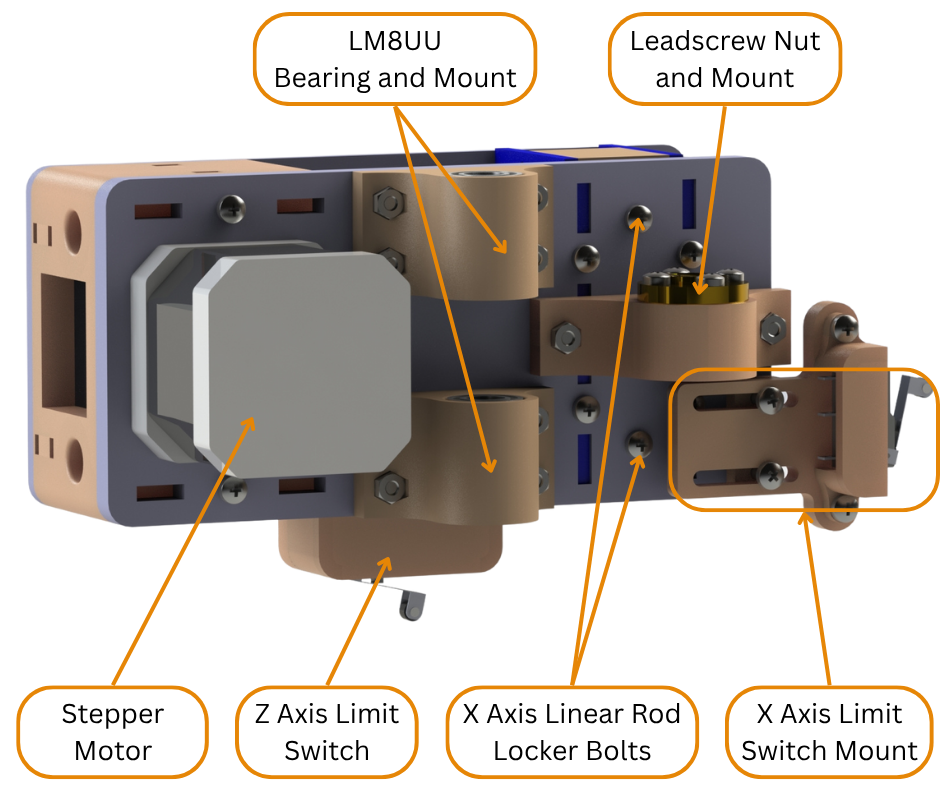
Fig.4
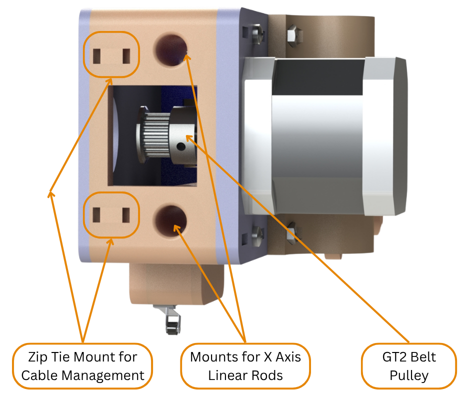
Fig.5
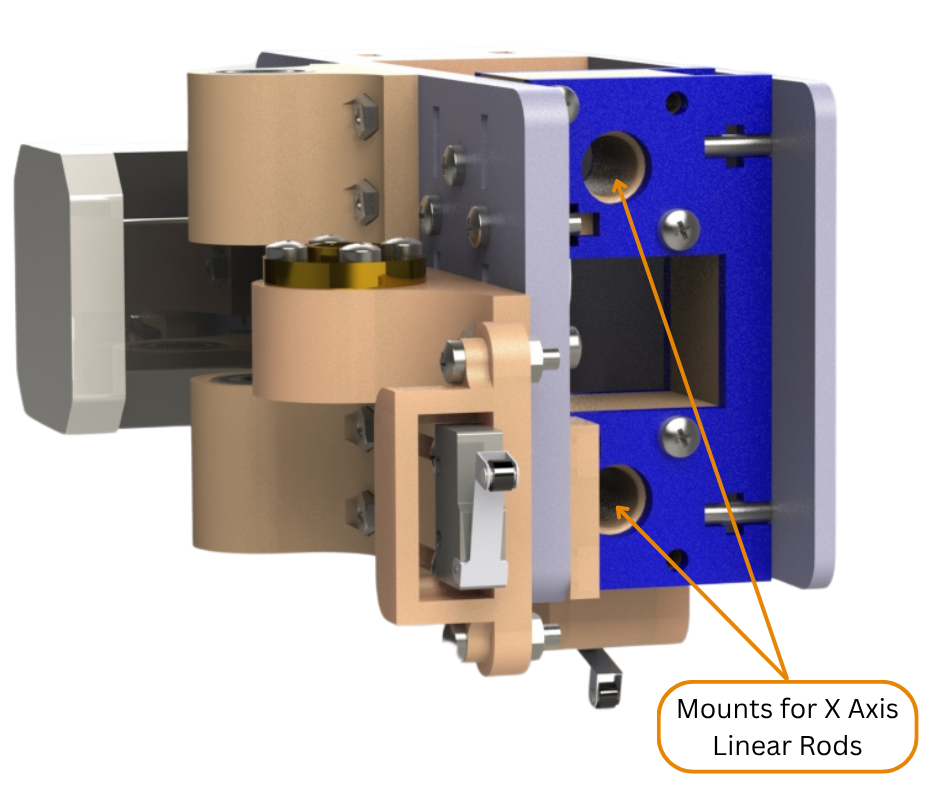
Fig.6
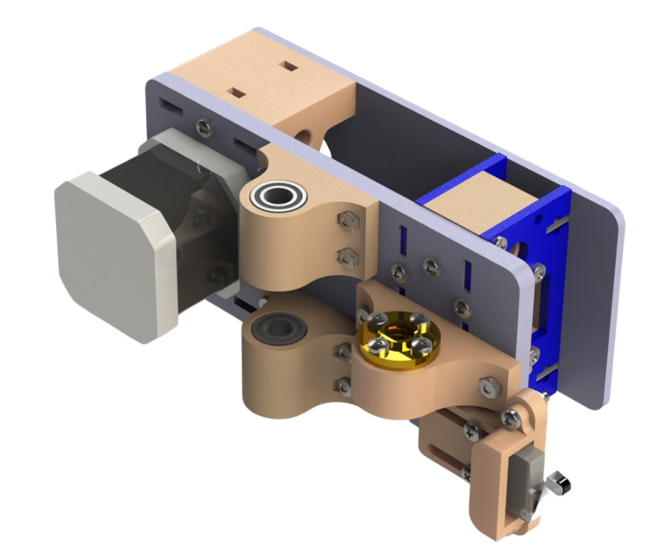
Fig.7
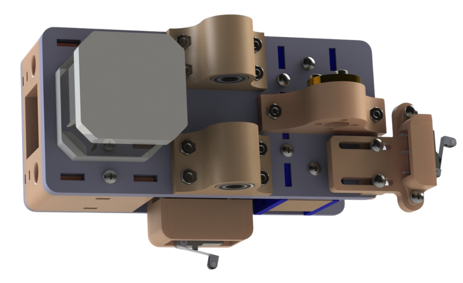
Fig.8
Fig.3 to Fig.8 show the X axis Motor mount. This part is an assembly of both laser cut acrylic parts and 3d printed parts. Fig.4, Fig.5 and Fig.6 highlights and labels all the parts connected to some 3mm thick laser cut acrylic panels that form the frame of the motor mount. The LM8UU bearing mounts are 3d printed parts that have LM8UU linear bearings press fit into them and then are then attached to the acrylic frame of the motor mount. Similarly the lead screw mount has an 8mm lead screw nut bolted to it. To help with the wiring management of the 3d printer, we decided to mount both the X axis and the Z axis limit switches on the X axis motor mount. This way the wiring for the X axis stepper motor, X axis limit switch and the Z axis limit switch are all contained in a single wire loom that can then be routed to the printer control box. These limit switches will be discussed further in this post. Fig.5 shows a 20 teeth GT2 pulley attached to the shaft of a nema 17 stepper motor that is attached to the motor mount. This stepper motor moves the Extruder/Tool mount along the X axis. It does this through the use of a GT2 timing belt. This timing belt (shown in Fig.22) is open ended. The ends of the belt are attached to the X axis Extruder/Tool mount. The belt also loops around the Drive Pulley attached to the stepper motor on the motor mount as well as an Idler pulley on the X axis Idler mount which will be discussed later in this post. Together this system of belt and pulleys allows the stepper motor to move the X axis Extruder/Tool mount along the X axis. As can be seen in Fig.2 the X axis motor mount and X axis Idler mount assemblies are connected together using 8mm stainless steel rods. To hold these rods in place, both these assemblies have 3d printed mounts for these rods that appropriately space these rods and lock them in place. Fig.5 and Fig.6 shows the linear rod mounts on the X axis motor mount assembly. Once the linear rods are installed in these mounts (Fig.23), linear rod locker bolts shown in Fig.4 are tightened whereby the rods are locked in place.
Fig.9
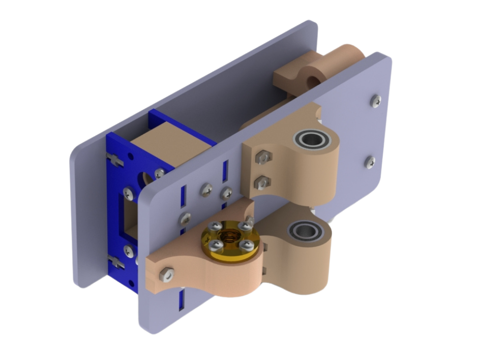
Fig.10
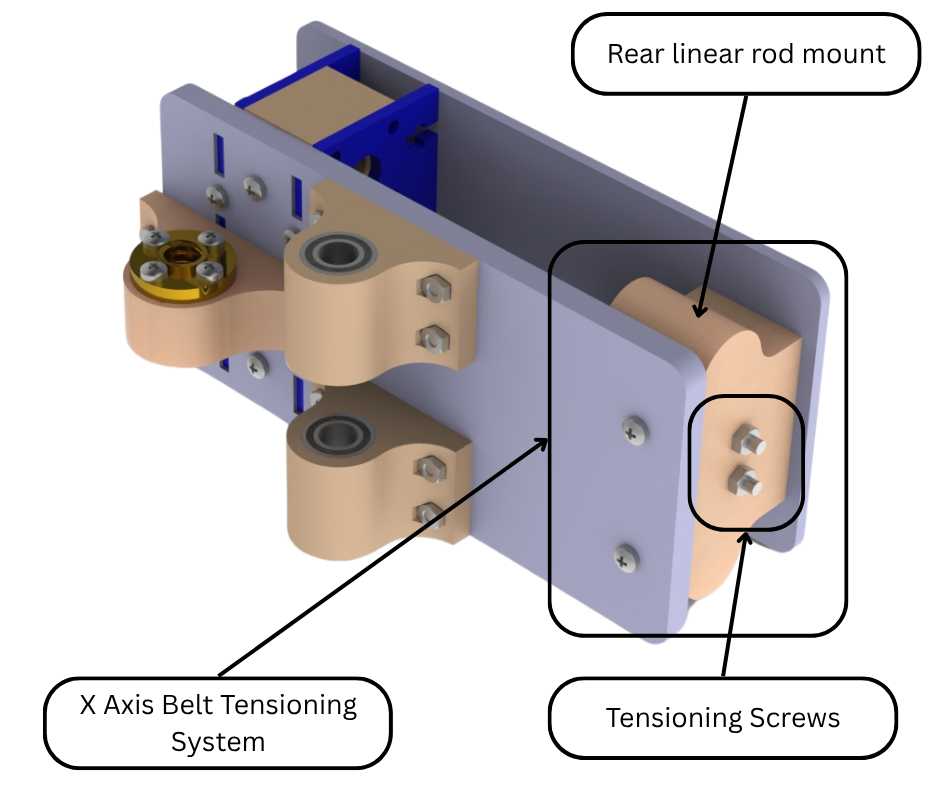
Fig.11
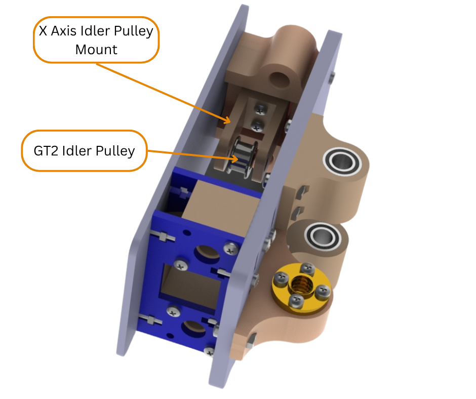
Fig.12
Fig.13
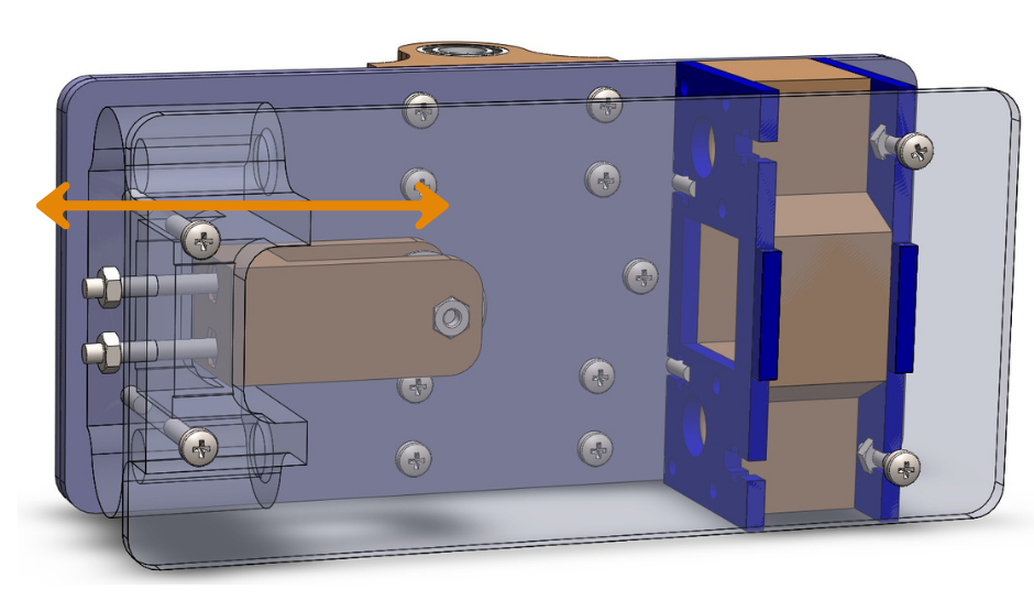
Fig.14
Fig.9 to Fig.14 show the X axis Idler mount assembly. This assembly is almost identical to the X axis motor mount assembly except for one component. Instead of having a stepper motor, the idler assembly has a belt tensioning system mounted to it. Fig.11, Fig.12 and Fig.14 show this belt tensioning system. This system consists of a pulley mount that has a GT2 idler pulley installed on it. This pulley mount has two long M3 bolts installed on it. These bolts then go through the rear linear rod mount. On the other side of the linear rod mount, these bolts interface with two M3 nuts. Tightening these M3 nuts pulls the Idler pulley mount towards these nuts and vice versa. The purpose of this tensioning mechanism is to keep the X axis timing belt loop taut and under tension. This ensures dimensional accuracy in the X axis as well as preventing the belt from slipping on the drive pulley and skipping steps. As discussed earlier, the timing belt loops around both the stepper motor pulley on the motor mount assembly and the idler pulley on the idler mount assembly. Once the timing belt has been installed, the two M3 nuts of the belt tensioning system are turned clockwise. This pulls the idler pulley mount inwards, causing the belt loop to stretch and become taut.
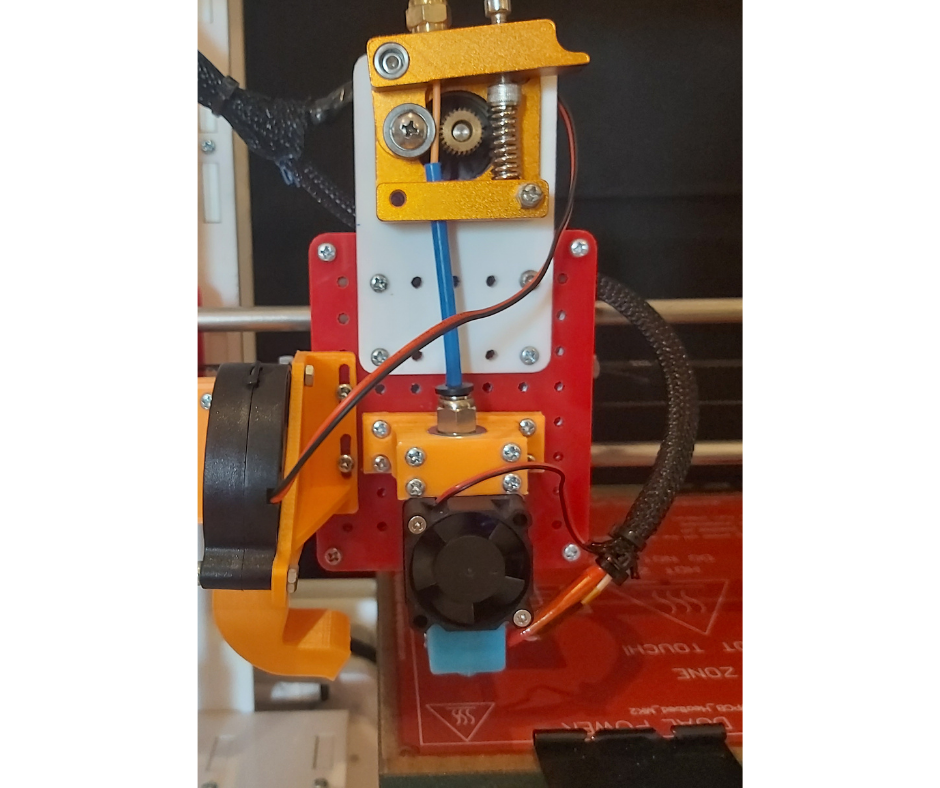
Fig.15
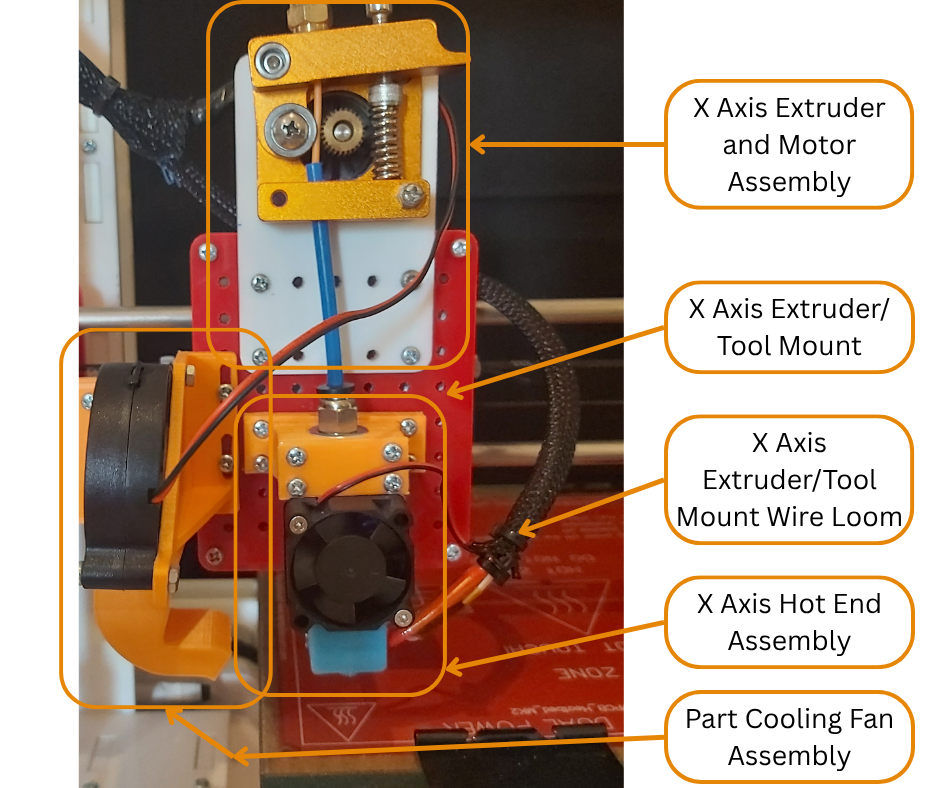
Fig.16
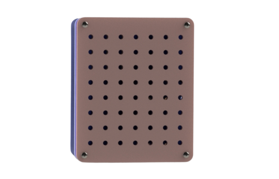
Fig.17
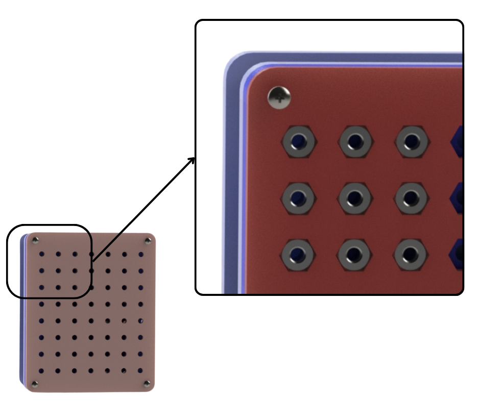
Fig.18
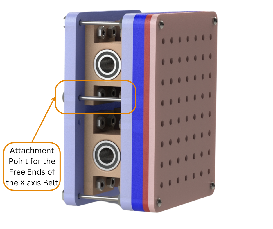
Fig.19
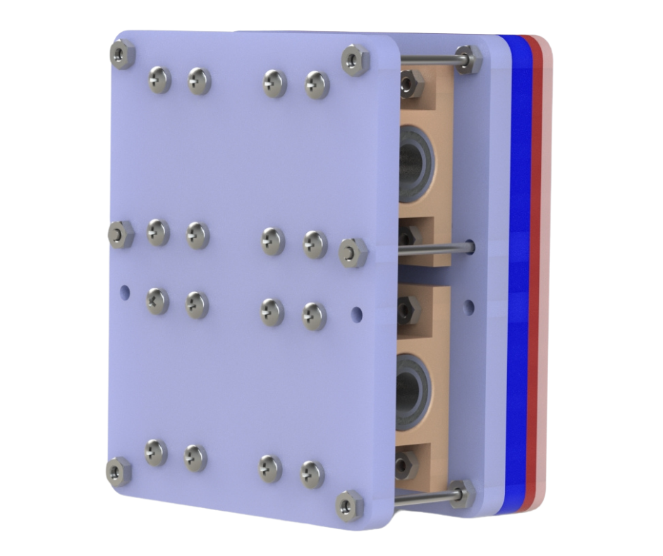
Fig.20
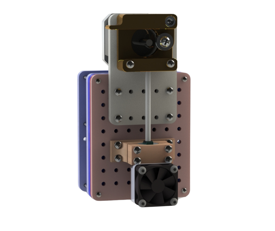
Fig.21
Fig.15 to Fig.21 shows the X axis Extruder/Tool mount assembly. As discussed earlier, the extruder/tool mount assembly is the movable component of the entire X axis gantry. We have designed this assembly to be modular and multipurpose. We have designed this mount such that one can attach any tool be it a 3d printing hot end assembly or a spindle with a cutting bit to be used in a CNC capacity. Fig.17 shows the front of this assembly. As can be seen there are multiple evenly spaced holes. Each of these holes has a captive M3 nut behind it as can be seen in Fig.18. This allows us to attach any of the aforementioned tools or any other accessories to the front of this extruder/tool mount. As can be seen in Fig.19, this assembly also consists of 3d printed LM8UU bearing mounts with the linear bearings installed in them. These bearings allow the extruder/tool assembly to travel along the X axis linear rods. Fig.19 also shows the mounting points for the free ends of the X axis timing belt which has been discussed earlier. Fig.21 shows the extruder/tool mount having a hot end assembly and stepper motor with extruder mounted to it.
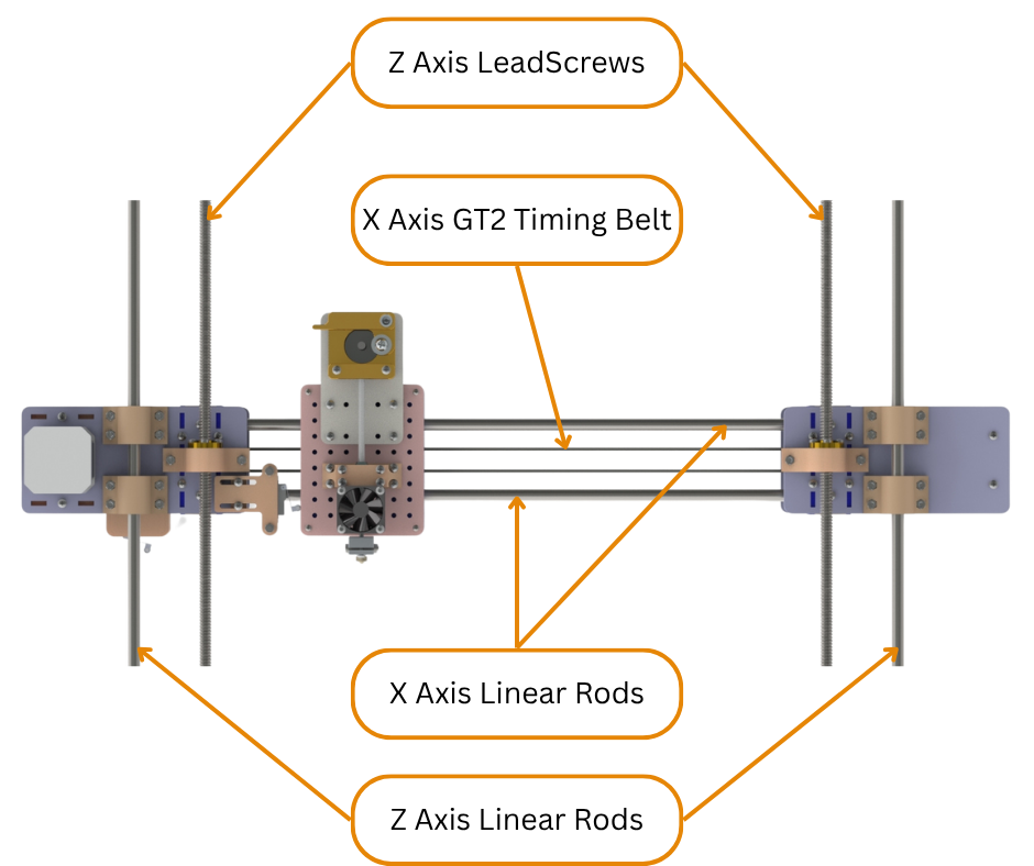
Fig.22
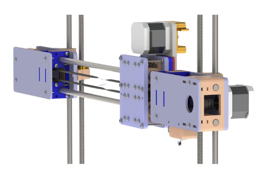
Fig.23
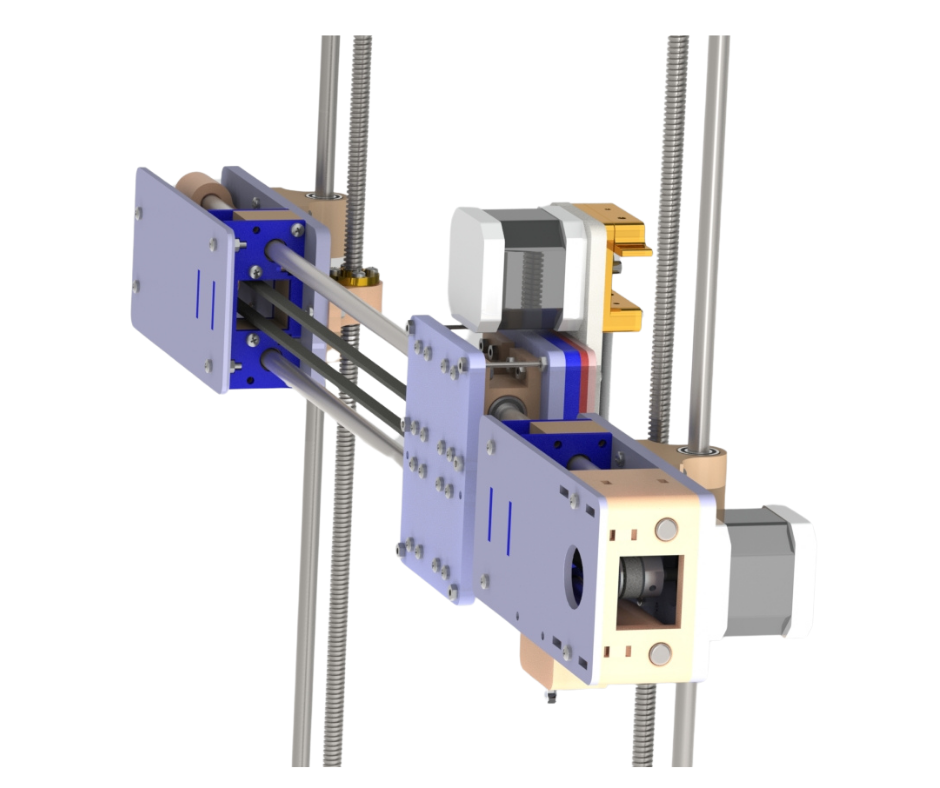
Fig.24
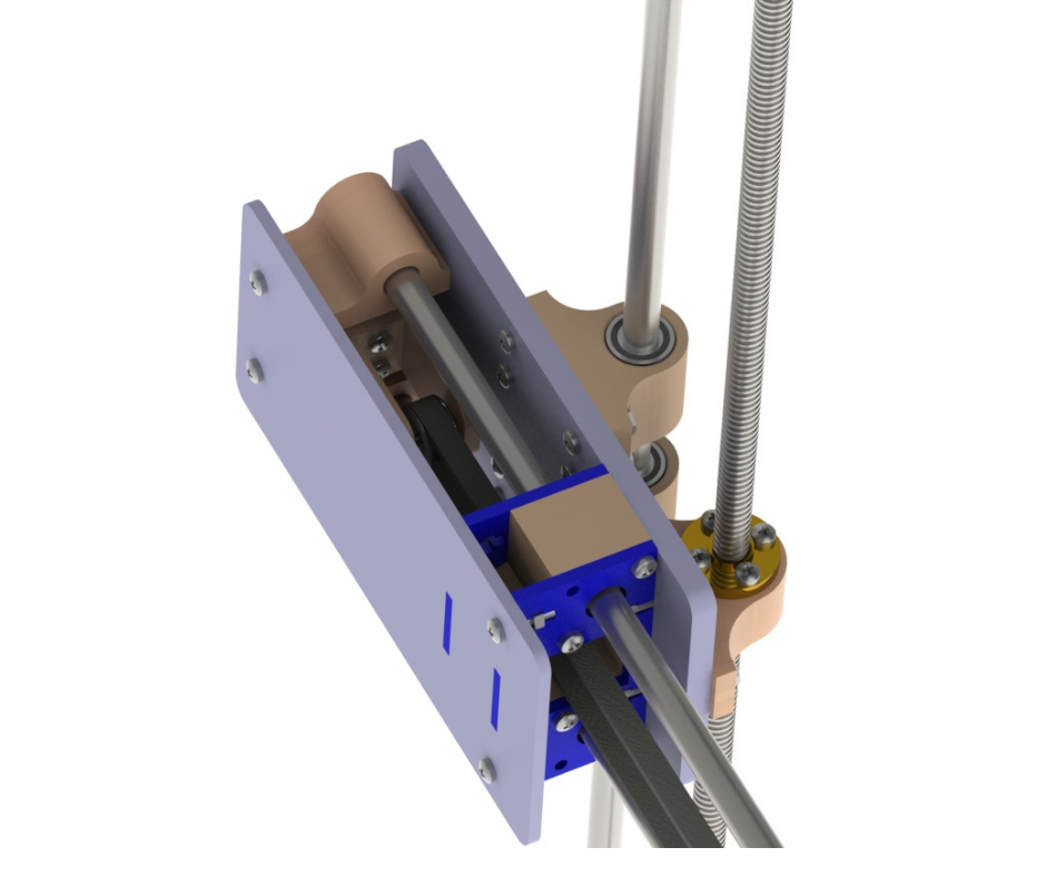
Fig.25
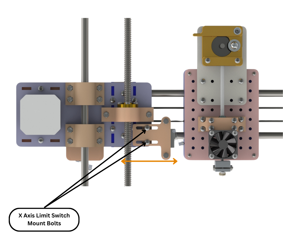
Fig.26
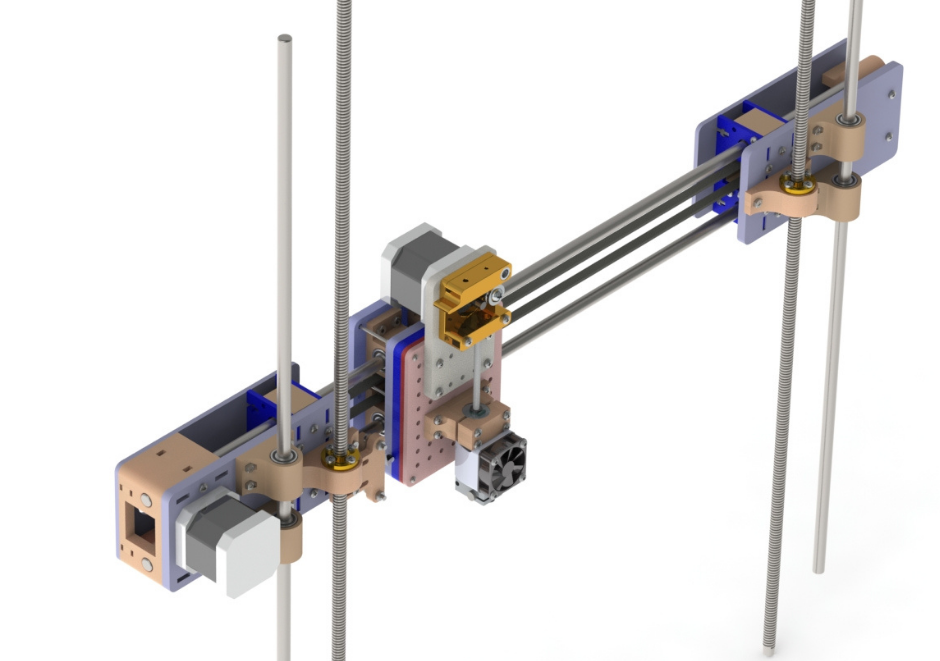
Fig.27
Fig.22 to Fig.27 shows the entire X axis gantry assembled. As can be seen in Fig.22 the entire X axis gantry travels along the Z axis linear rods. The two Z axis lead screws interface with the lead screw nuts mounted to both the X axis motor mount and X axis idler mount assemblies. These two lead screws are attached to the Z axis stepper motors as discussed in an earlier post on the Z axis gantry. The two Z axis stepper motors are synchronised with each other. This means that both the Z axis motors spin in the same direction and by the same amount. So when the two stepper motor shafts spin, they also turn the lead screws they are attached to. When the lead screws turn they move the lead screw nuts attached to them up or down vertically depending on the spin direction. And since the lead screw nuts are attached to the motor and idler mount assemblies, these assemblies also move up or down. This in turn moves the entire X axis gantry vertically up or down along the Z axis linear rods. Fig.24 and Fig.25 show the X axis belt looping around the drive pulley in the X axis motor mount and the idler pulley in the X axis idler mount assemblies respectively. These figures also show the X axis linear rods installed.
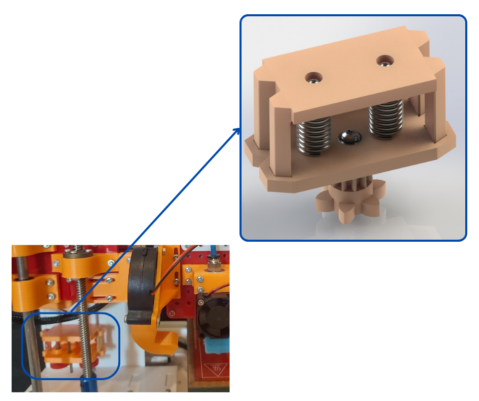
Fig.28
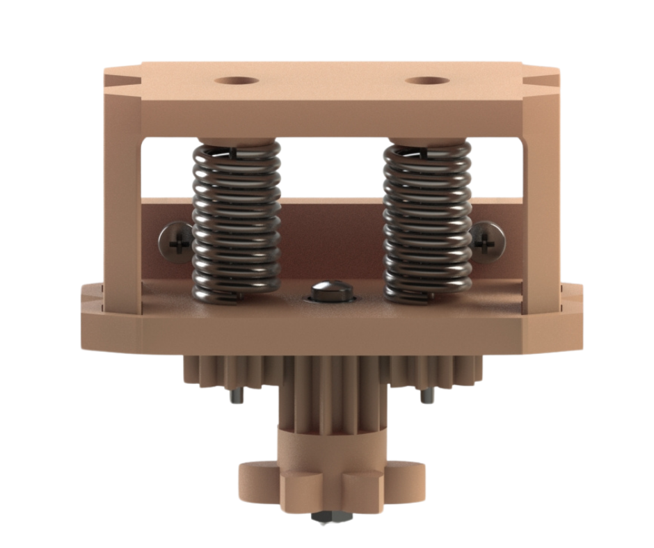
Fig.29
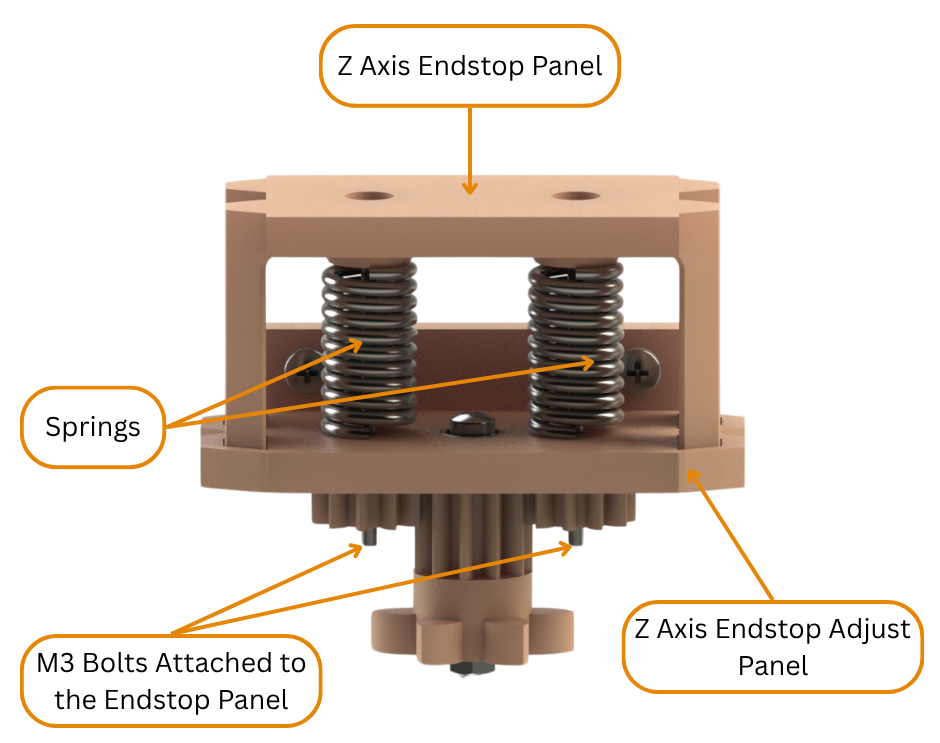
Fig.30
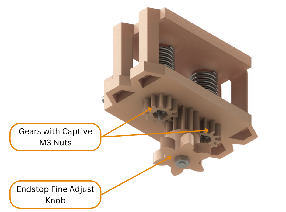
Fig.31
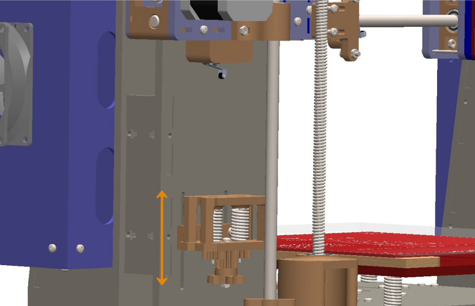
Fig.32
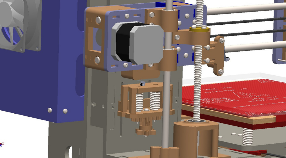
Fig.33
Now we will discuss the workings of the X axis and Z axis limit switches. In every 3d printer there is a coordinate system in which the 3d printer knows where all of its moving components are. It knows this because at the start of every 3d print the 3d printer goes through a ‘homing’ sequence where it determines the origin point of its coordinate system. The printer then references everything to this origin point. Most printers have its origin at the bottom left corner of the printbed. The origin point comprises the starting point of the X, Y and Z axis. In the X axis the origin is determined in the homing sequence by moving the extruder/tool mount towards the motor mount until it activates the X axis limit switch whereby the homing sequence for the X axis finishes. This is shown in Fig.26 and Fig.27. In the Y axis the origin is determined by moving the printbed assembly (discussed in an earlier post) towards the Y axis stepper motor until it activates the Y axis limit switch whereby the homing sequence for the Y axis finishes. In the Z axis the entire X axis gantry is lowered towards the printbed assembly until the Z axis limit switch is activated. This is shown in Fig.32 and Fig.33.
All the three limit switch positions are adjustable in our 3d printer. We have added this feature to allow for the printer to be upgraded or components to be changed or upgraded in the future. Changing components such as hotends, print bed surfaces, etc may require the origin of the printer to be shifted in either axes. The adjustability of the limit switches allows us to be able to shift the origin point if the need arises. The adjustability of the Y axis limit switch has been discussed in an earlier post on the Y axis. The X axis limit switch can be adjusted by loosening the bolts shown in Fig.26 and sliding the limit switch mount left or right to the desired position and then retightening the mentioned bolts. In the Z axis the Z axis limit switch mounted on the X axis motor mount activates when the switch comes in contact with the Z Axis end stop shown in Fig.28 to Fig.33. This end stop mechanism has two adjustment levels. There is the coarse adjustment where the whole end stop assembly can be moved up or down along the slots in the frame of the printer as shown in Fig.28 and Fig.32. This is to bring the X axis gantry down to a point where the hot end or tool in the extruder/tool mount barely touches the print surface on the Y axis print bed assembly. Then there is a need for fine adjustment so that the hot end nozzle or tool tip only just touches the print bed surface. To achieve this fine tuning, the adjustment knob on the endstop assembly shown in Fig.31 is turned counter clockwise. This turns the smaller gears clockwise simultaneously. These gears each have an embedded M3 nut that interfaces with bolts that are attached to the endstop panel (Fig.30). When the nuts rotate clockwise they pull the bolts and the endstop panel towards the end stop adjust panel. The springs maintain this position by exerting an upwards force to the downwards force from the gears and the M3 nuts. So as a whole turning the adjustment knob on the endstop assembly lowers the endstop panel. This way the X axis gantry can be lowered even further until the hot end or tool tip just touches the print surface whereby the Z axis homing is completed.