To better understand the context behind this project, please read our project post titled “Desktop CNC Machine Version 1.0”.
When milling printed circuit boards (PCBs) with our desktop CNC we noticed that sometimes when a circuit track was milled the cut edge would have burrs. While researching this issue we learned that in addition to feed rates the RPM (revolutions per minute) of the tool was very important as well. We were using a 775 DC motor with an er11 collet to hold the cutting/milling tool. Although a 775 DC motor is quite powerful and is often used to power portable drills, it had a max RPM of 12000 at 12v. At 24V it could technically do double the RPM but that came with a lot of noise and chatter. Ideal milling/cutting RPM for PCBs lie in the range of 10000 to 100000 RPM. RPM at the higher end of this range leads to better accuracy especially when using smaller tools.
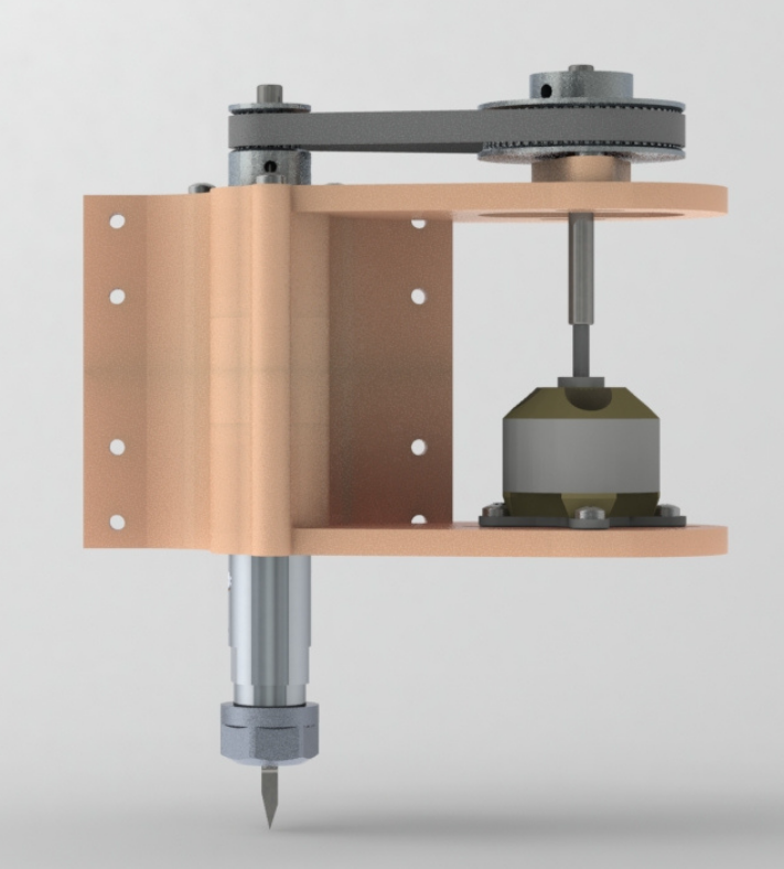
Fig.1
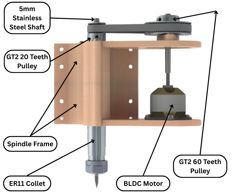
Fig.2
So to increase our RPM range and also allow for control of RPM speed of the tool, we designed a custom spindle for our desktop CNC machine. The version 1 of the new spindle design is shown in Fig.1 and labelled in Fig.2. The body or frame of our new spindle consists of 2 3D printable parts. The reason for making it in two parts is because bearings have to be installed inside and also because it would make 3D printing easier. The two parts are bolted together with 3mm bolts as shown in Fig.3.
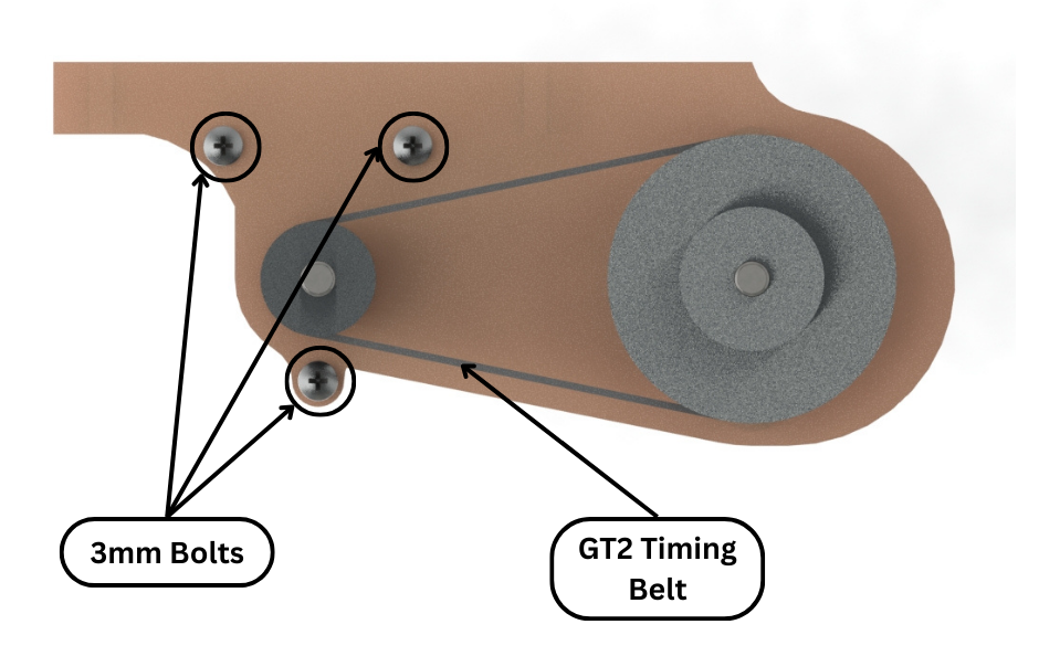
Fig.3
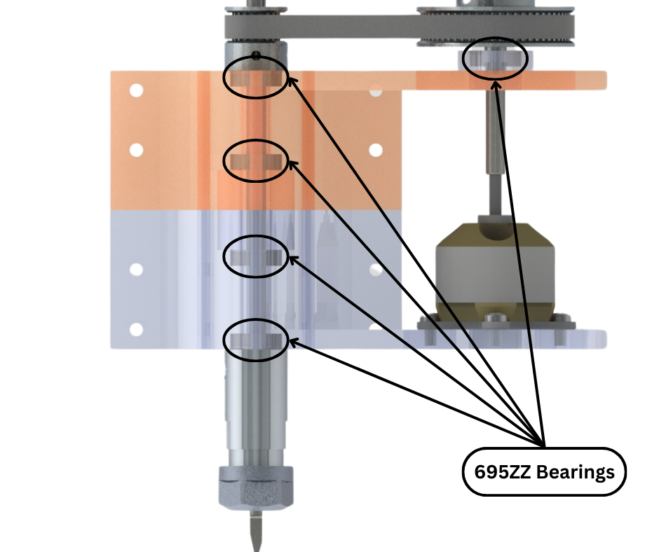
Fig.4
There are multiple 695zz bearings installed on and inside the frame of the spindle as shown in Fig.4. These bearings are there to hold the main 5mm spindle shaft in place and to make sure that it spins true and that it does not wobble. The main spindle shaft has an ER11 collet attached to one end and a 20 teeth GT2 pulley at the other end. The two components and the bearings lock the spindle shaft in place.
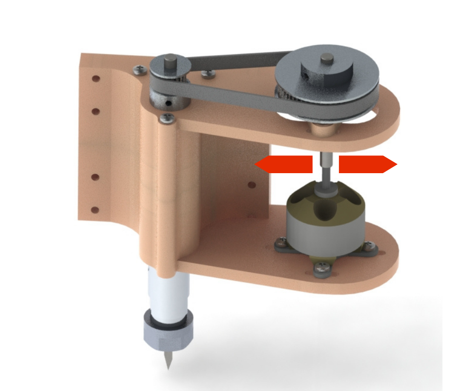
Fig.5
There is a BLDC motor installed on slots designed into the frame to allow the motor to slide as shown in Fig.5. This is to allow the motor to be pulled so that the GT2 belt becomes taut and then the motor bolts can be tightened to lock it into place. We chose a BLDC motor to power our new spindle because it has a much higher RPM than the 775 DC motor. Also its speed can be easily and finely controlled. The motor shaft is connected to a 60 teeth GT2 pulley as shown in Fig.2. This larger pulley is connected to the smaller pulley on the main spindle shaft via a closed loop GT2 timing belt. As a result we can achieve an even higher output spindle speed than the BLDC motor because of the 3 to 1 increase in speed due to the pulleys.
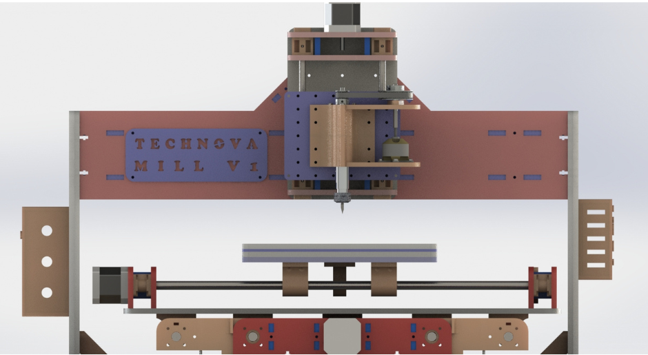
Fig.6
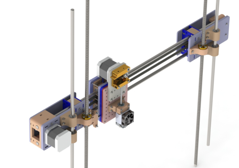
Fig.6 shows how the new spindle would look when connected to our CNC machine. This is just the design of the spindle completed. We will 3D print and assemble this design and then test it out to see if it matches our requirements and if the two part design is rigid enough to prevent chatter and vibrations.