If you have not read our project blog post regarding the development of our CNC machine, we would recommend that you read that so that you can have a background on the design of our CNC machine which we will refer to here.
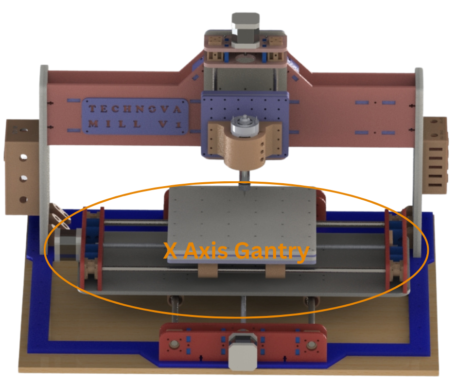
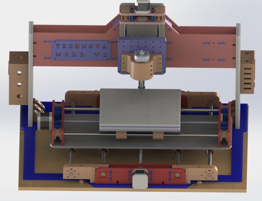
Fig.1
Fig.1 shows the design of our CNC machine just before this upgrade. This original design was put through a lot of tests. During testing and use we found out some shortcomings of our original design. One of the bigger issues with our design is highlighted in Fig.2. As can be seen from Fig.1 our X axis Gantry is mounted on two linear rods and can move in the Y axis. Each of the linear rod is some distance away from the end of the X gantry closest to it. This leads to a significant amount of X gantry overhang at both ends. Now if the X gantry was constructed from a stronger material like steel this overhang would not be an issue. But since our X gantry and the entire machine itself is constructed from 6mm thick acrylic sheets and 3D Printed parts, this overhang causes the X gantry to bend under load.

Fig.2
As can be seen in Fig.2 when the spindle applies a downward force during cutting/engraving on a workpiece being held on the workbed, this force is transmitted via the X axis linear rods to the two ends of the X gantry. This force is then applied on the ends of the X gantry which causes a rotational moment on either end of the X gantry about each of the Y axis linear rods. This causes the X gantry to bend down from the ends and bend up from the middle.
This issue results in uneven depth of cut in the workpiece. This is because when the workbed moves along the X gantry, due to the bending of the X gantry the height of the workbed in relation to the spindle changes slightly. This might not cause much noticeable difference when doing milling or engraving in acrylic or wood for decorative purposes. But when milling PCBs where the copper layer is about 35 microns thick, this bending issue has a significant effect.
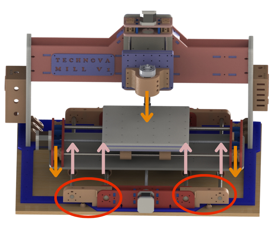
Fig.3
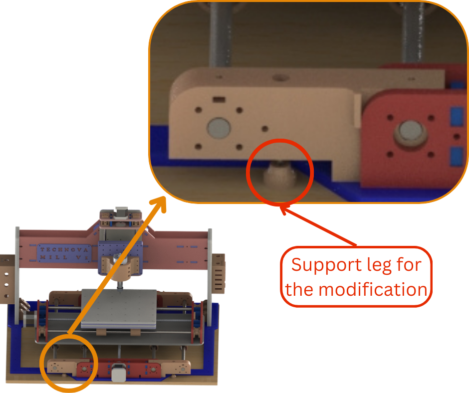
Fig.4
Fig.3 shows a possible solution that we implemented on our CNC machine. Now this is just a temporary “patch” to version 1 of our machine because we need to extensively test this solution before it becomes a permanent addition to version 2 of our design. As can be seen in Fig.3 we have added two extra Y axis linear rods to our CNC machine. One extra linear rod on each half of the X gantry. To attach these linear rods to the existing CNC (version 1) base we designed a 3D Printable mount for the linear rods. These mounts are circled red in Fig.3. These mounts attach to the existing frame as shown in Fig.3. Four extra linear bearings are also installed on the X gantry, So that the X gantry can utilize the additional linear rods. The mounts also feature support legs as shown in Fig.4 that reduce the extra load of the additional linear rods and bearings on the existing machine frame.
These extra rods reduce the amount of overhang on either end of the X gantry significantly. This reduces the ability of the X gantry to bend. The extra rods significantly minimizes the amount of rotational moment experienced by the ends of the X gantry about the Y axis when under load. This is because any rotational moment that occurs at the X gantry ends is counteracted by the second linear rod at each half of the X gantry. This is illustrated in Fig.3 by peach colored arrows. Now if excessive downward pressure is applied to the workbed the X gantry can still bend at the ends. But for the normal tasks that this machine is designed for the forces will cause negligible bending.