In this post we will showcase a prototype of a servo drive that we designed and manufactured using 3D Printing. We wanted a low cost yet powerful servo for application in our future projects requiring precise movements with structural rigidity. The issue with commercially available low cost hobby servos is lack of power and lack of output rigidity. To add greater output torque to our servo drive, we have used two 24v geared DC motors to drive the output of the servo. The output torque is further increased by using a 2 to 1 gearing ratio between the output shaft and the DC motors. To increase the rigidity of the output of our servo drive, we used a thrust bearing assembly to ensure that the output shaft of our servo can handle uneven loads and large radial and axial loads. To provide readings on the rotational position of the output to the micro-controller, we have used a multi turn precision potentiometer coupled directly to the output shaft. The micro-controller uses this data and controls the DC motors using PID control algorithm such that the output shaft moves precisely to the position that we tell the micro-controller. An important feature of this servo drive is that it is I2C communication enabled. This means that if we have multiple of these drives, we can simply assign each of them a unique address and control them all using only two communication wires by daisy chaining all the drives together.
The Design
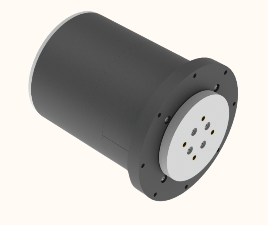
Fig.1
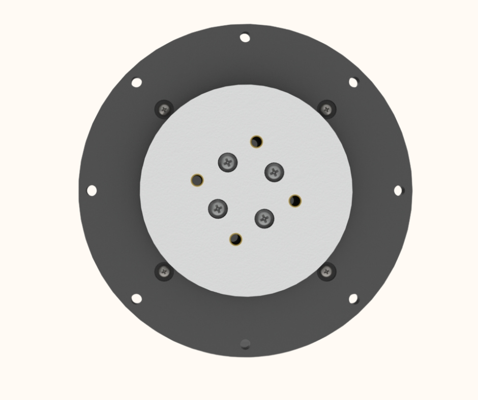
Fig.2
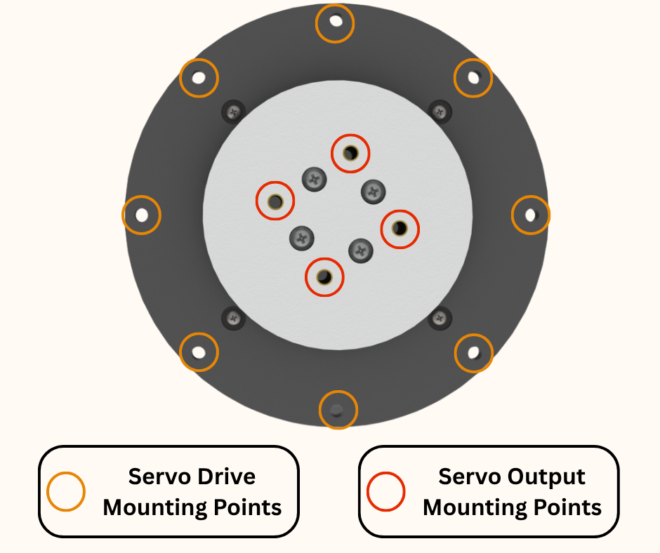
Fig.3
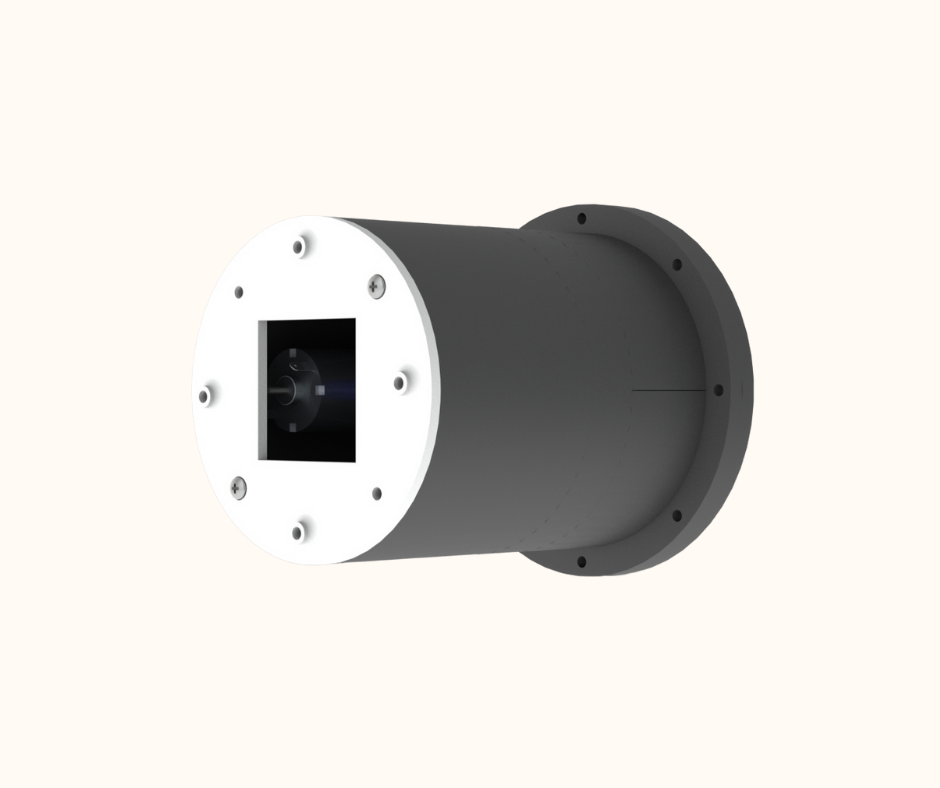
Fig.4
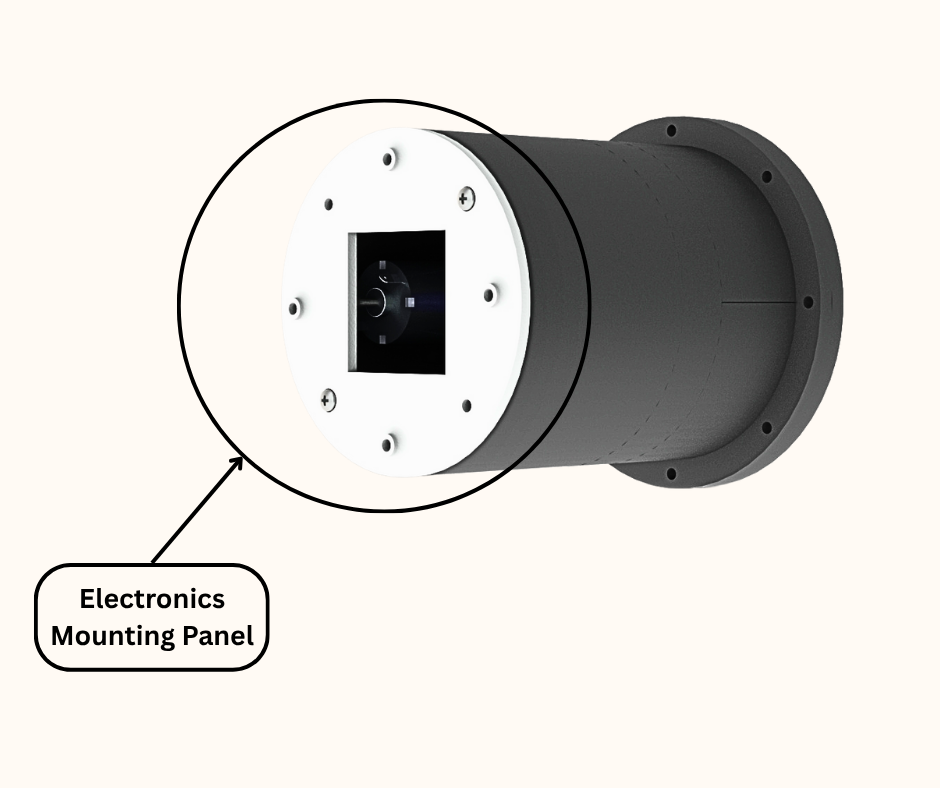
Fig.5
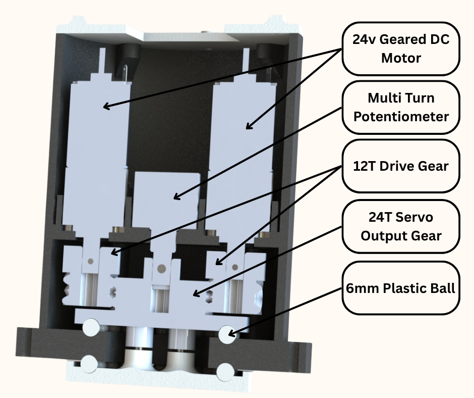
Fig.6
Fig.7
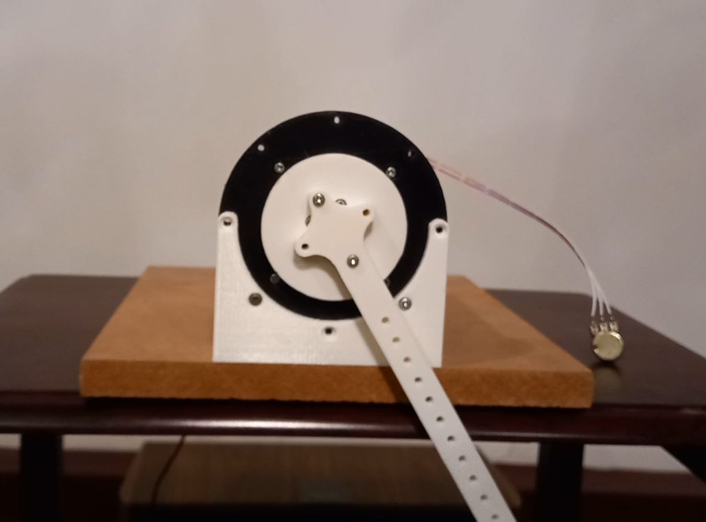
Prototype
Fig.8
Fig.9
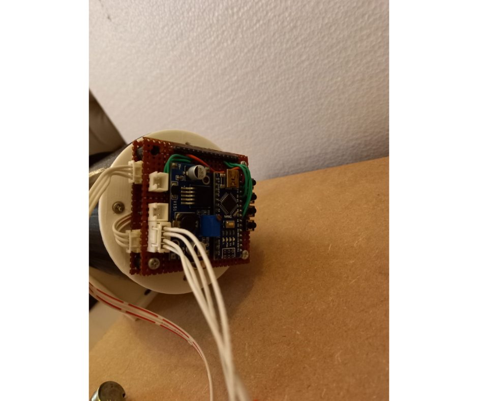
Fig.10