In this post we will discuss our work on developing a simple servo driven 3d printable gripper that we designed in Solidworks. A couple of days ago a client reached out to us and asked us to design for them a simple gripper that they can 3D print and use in their robotics project. This was a great opportunity for us to check off an item off our to-do list as well. We also needed a gripper for our own custom designed robotic arm. So the completion of this project would fulfill these two objectives.
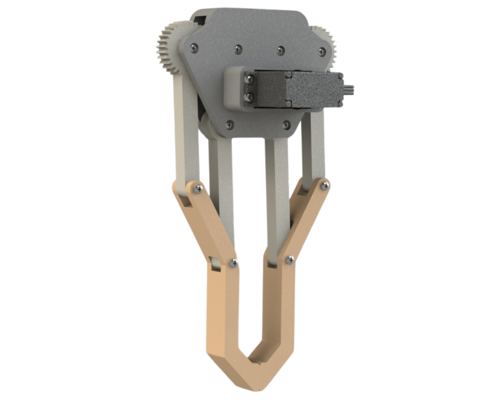
Fig.1
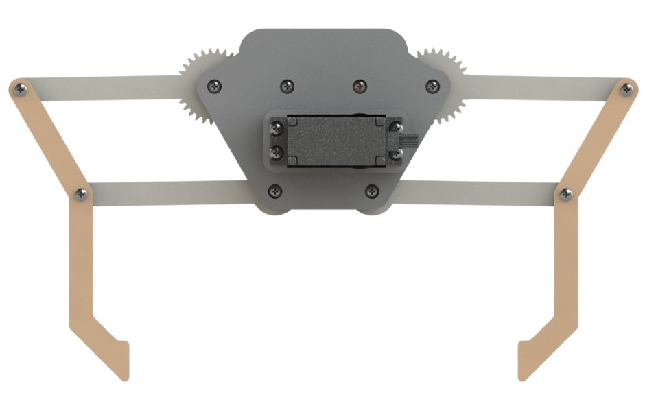
Fig.2
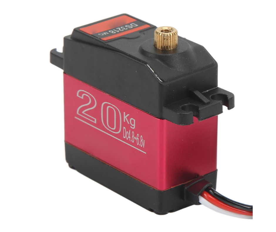
Fig.3
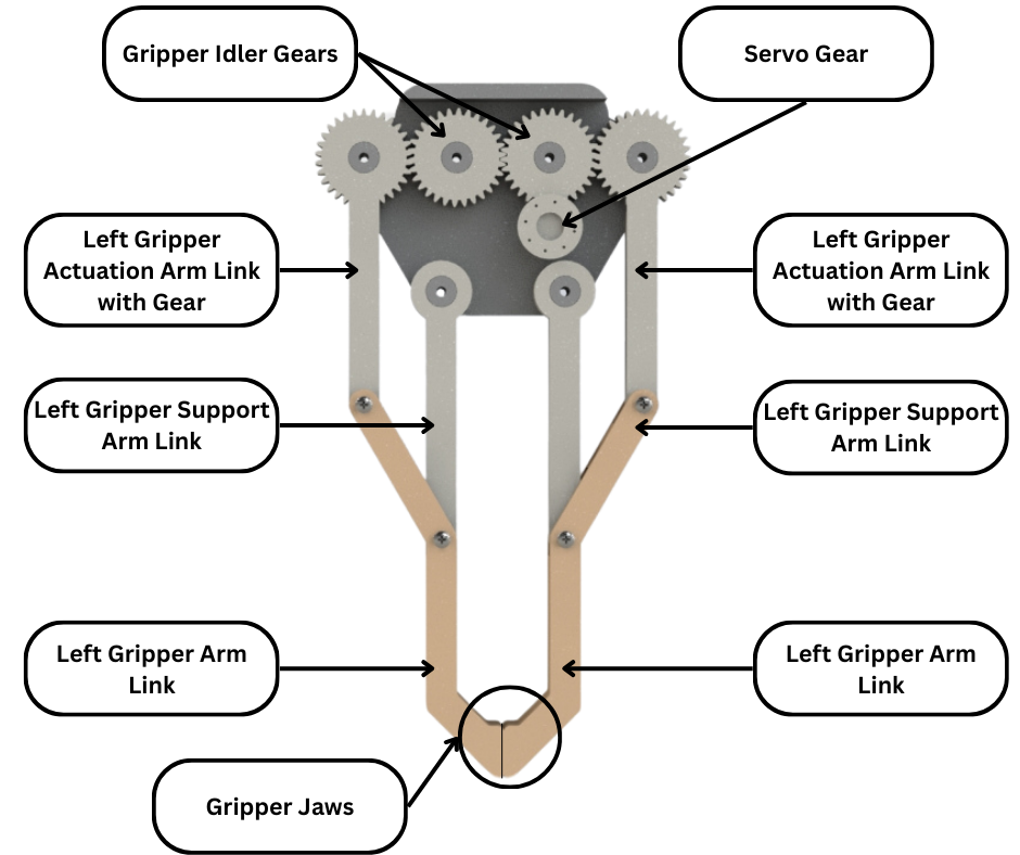
Fig.4
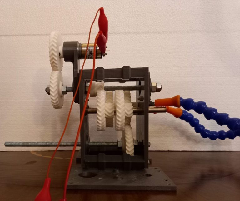
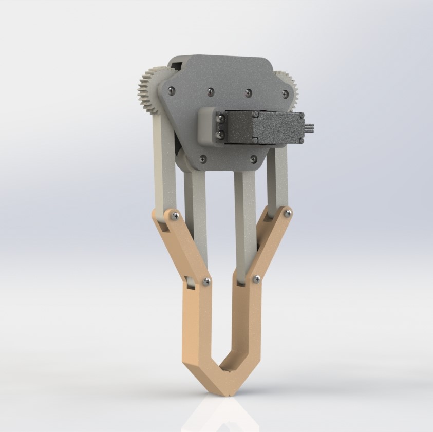
Fig.1 and Fig.2 shows the design of a simple pincer style gripper for robotic applications. This gripper is actuated using a DS3218MG high torque servo shown in Fig.3. Fig.4 shows the gripper design with the inner gears visible and everything labeled. The servo shown in Fig.1 turns the servo gear. The servo gear rotates the right idler gear which in turn rotates the left idler gear. Therefore the direction of the idler gears is opposite to each other. The idler gears then each rotate the gripper actuation arm that is coupled to it. Since the idler gears have opposite rotational direction to each other, similarly the left and right actuation arms also have opposite rotational direction to each other as shown in Fig.5.
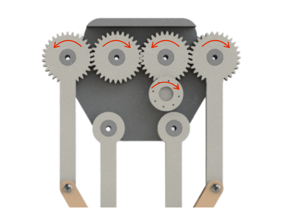
Fig.5
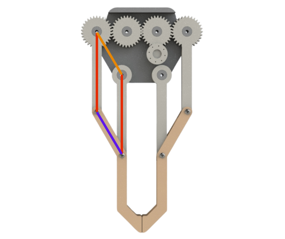
Fig.6
The actuation arm link of each side then moves the gripper arm link that it is connected to. The gripper arm link is moved in a way such that it maintains its rotational orientation and does not rotate or twist. This is made possible by the support arm linkages on each side of the gripper. The connection points of the actuation arm and support arm form a parallelogram when connected together as shown in Fig.6. Since the side of the parallelogram coloured orange is fixed by design, the side coloured blue will always remain parallel to it even when moved. This is known as the parallelogram mechanism and it ensures that the gripper jaws remain parallel to each other at all times.
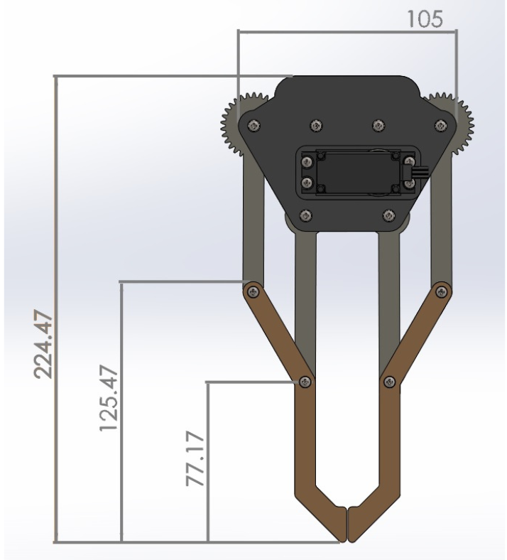
Fig.7
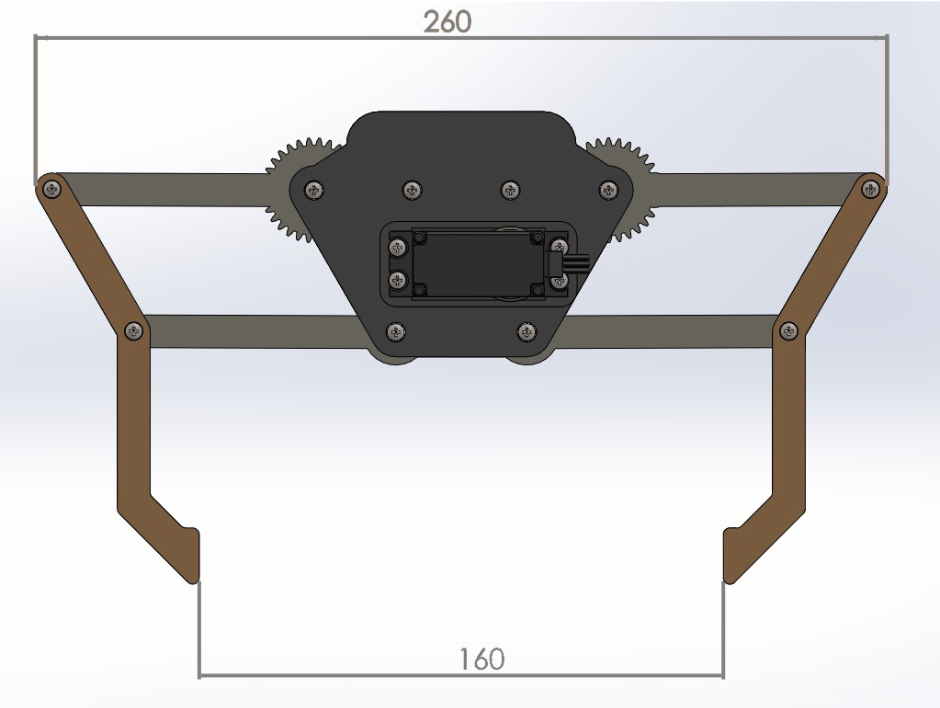
Fig.8
Fig.7 and Fig.8 show the dimensions of our gripper. All the dimensions are in millimeters. The maximum opening distance of the jaws in our gripper is 16 cm. Our client wanted the gripper to have a minimum jaw opening distance of 12 cm, so our design fulfills that requirement comfortably.
Working Principle
Fig.9
Fig.10